How to Choose the Right AC Motor for Your Application
Choosing the right Ac Motor begins with the machine, not the catalog. A conveyor carrying dusty cartons needs different protection from a clean laboratory fan. Load torque, starting demand, speed range, duty cycle, voltage, and available space must be examined together. One overlooked detail can turn a reliable installation into an expensive heat source.
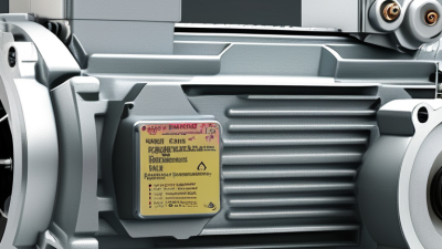
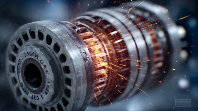
Nikola Tesla, the pioneer of alternating-current motors, captured the central principle: “The rotating magnetic field is the basis of the induction motor.” That field must match the application’s mechanical demands. A three-phase induction motor may suit a pump running for long hours. A single-phase motor may fit a small ventilation unit. Variable-speed work often requires an inverter-duty motor, proper insulation, and compatible control settings. Efficiency matters, but so do starting current, noise, maintenance access, and ambient temperature. A motor can be efficient on paper and still perform poorly in a cramped enclosure.
Real selection also requires honest field experience. Measure the driven load when possible. Do not rely only on the old nameplate. Belts stretch. Bearings age. Pumps clog. These issues change motor requirements. Sometimes, the “correct” replacement is not the same size or rating. That can feel uncomfortable. Recheck the assumptions.
This guide outlines a practical path for comparing Ac Motor types, ratings, controls, and protection levels. It also highlights common selection mistakes, including oversizing, ignoring duty cycles, and pairing unsuitable drives. The goal is simple: dependable performance, controlled operating costs, and fewer surprises after installation.
Define Load Requirements: Torque, Speed, Duty Cycle, and Starting Demand
How to Choose the Right AC Motor for Your Application
Define Load Requirements: Torque, Speed, Duty Cycle, and Starting Demand
Begin with the load, not the motor catalogue. Measure the torque required at the shaft during normal operation. Then identify peak torque during acceleration, jams, or sudden material changes. Torque equals force multiplied by radius, but real machines rarely behave perfectly. Record operating speed, required acceleration time, and the load’s inertia. A conveyor carrying uneven boxes needs different performance from a fan with a steady airflow.
Duty cycle also matters. Note running time, rest periods, starts per hour, and speed changes. A motor running continuously may need a different thermal rating than one operating for short bursts. Starting demand deserves special attention. High-inertia equipment can require substantial starting torque before reaching working speed. Check voltage conditions, available current, and the permissible starting method. A motor that starts well in a workshop may struggle when cables are longer or the supply is weaker. Small details matter.
Tips: Create a simple load profile. Include normal torque, peak torque, speed, and operating time. Add a safety margin, but avoid oversized selection. Excess capacity can increase cost and reduce efficiency. Recheck your assumptions with measured data. A neat calculation can still mislead. If the load changes often, test the motor under the hardest realistic condition. Document the results for future maintenance decisions.
Select Motor Type: Induction, Synchronous, and Single-Phase Designs
Choosing the right AC motor starts with the load, supply, and operating environment. Motor type matters more than many selection charts suggest. Measure starting torque, running speed, duty cycle, and available voltage before comparing models. A motor that looks efficient may struggle with repeated starts or sudden load changes.
Induction motors are dependable for pumps, fans, conveyors, and workshop equipment. Their simple construction usually means easier maintenance and reasonable cost. However, speed drops slightly under load, and starting current can be high. Synchronous motors maintain nearly constant speed, which helps with precision equipment, timing systems, and compressors. They may also support power-factor correction. Yet their starting method can be more complex, and poor sizing reduces that advantage. It is tempting to choose synchronous performance too quickly.
Single-phase motors fit homes, small shops, and equipment without three-phase power. Capacitor-start designs provide stronger starting torque, while shaded-pole designs suit small fans and light loads. Check whether the motor can handle frequent cycling. A small motor may run quietly but overheat when ventilation is restricted. In practical testing, I would measure casing temperature after a realistic operating period, not only during a short demonstration. Mounting position, ambient heat, voltage fluctuation, and shaft alignment also affect service life. A technically correct selection can still fail in a dusty, cramped enclosure.
Estimate Speed from 50/60 Hz Supply and 2–8 Pole Motor Configurations
Choosing an AC motor begins with supply frequency and pole count. Use the synchronous-speed formula:
speed = 120 × frequency ÷ poles.
At 50 Hz, a two-pole motor reaches 3,000 rpm, while four-, six-, and eight-pole motors reach 1,500, 1,000, and 750 rpm. At 60 Hz, the figures become 3,600, 1,800, 1,200, and 900 rpm.
Real motors run slower. Slip increases with load, temperature, and rotor design. A four-pole induction motor rated at 50 Hz may operate near 1,440 rpm, not exactly 1,500 rpm. That difference matters when selecting pumps, fans, conveyors, or gearboxes. I have seen sizing errors occur when engineers use nameplate speed without checking operating torque. It is an easy mistake.
Energy use deserves equal attention. The U.S. Department of Energy’s Motor Systems Market Assessment reports that motor systems consume about 68% of industrial electricity in the United States. The International Energy Agency also identifies motor-driven systems as a major global efficiency opportunity. Choose the lowest practical speed before adding mechanical reduction, but verify starting torque and duty cycles. An eight-pole motor may reduce noise and wear, yet it can require a larger frame. Frequency tolerance, voltage variation, ambient temperature, and efficiency class should be recorded before approval. Calculations are useful, but field measurements are better. Industry data can guide a decision, not replace one.
Size Power with P = Tω and Verify NEMA MG 1 Frame Compatibility
Choosing an AC motor starts with the load, not the catalog. Start with the load. Measure its required torque and speed at the shaft. Use P = Tω, where power equals torque multiplied by angular speed in radians per second. This calculation gives a practical baseline for motor sizing. Do not guess. A conveyor may need modest running power but high starting torque when fully loaded. Pumps, fans, and compressors also behave differently during acceleration. Check duty cycle, starts per hour, ambient temperature, altitude, voltage, frequency, and service factor. A larger motor is not always safer; it can increase inrush current and reduce operating efficiency.
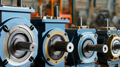
Frame compatibility requires careful dimensional verification under NEMA MG 1 requirements. Compare frame size, shaft height, shaft diameter, shaft extension, keyway, mounting holes, and overall length. Confirm whether the motor uses a foot-mounted, face-mounted, or flange-mounted arrangement. Review enclosure type and cooling method, especially around dust, moisture, or washdown areas. I once approved a replacement after checking only horsepower and voltage. That shortcut failed. The shaft extension was longer, creating alignment problems and extra coupling load. Measure twice. Record the driven equipment’s actual dimensions, not only its old nameplate. A qualified engineer should verify the final selection, including overload protection and starting performance, before installation.
How to Choose the Right AC Motor for Your Application - Size Power with P = Tω and Verify NEMA MG 1 Frame Compatibility
| Application |
Load Type |
Required Mechanical Power |
Operating Speed |
Angular Speed, ω |
Calculated Shaft Torque, T |
Recommended Motor Rating |
Typical NEMA Frame |
Frame Compatibility Verification |
| Process water pump |
Continuous centrifugal load |
7.5 kW |
1,750 r/min |
183.3 rad/s |
40.9 N·m |
7.5 kW, 4-pole, three-phase motor |
213T, subject to enclosure and pole-count confirmation |
Pass when verified: shaft center height, shaft diameter, shaft extension, bolt-hole pattern, and C-dimension must match the existing pump base and coupling. |
| Conveyor |
Constant-torque duty with frequent starts |
5.5 kW |
1,450 r/min |
151.8 rad/s |
36.2 N·m |
7.5 kW motor if acceleration and starting margin are required |
213T or the applicable metric-equivalent mounting size |
Verify carefully: starting torque, thermal duty, stopping method, gearbox input dimensions, shaft loading, and the frame’s mounting-hole pattern. |
| Ventilation fan |
Variable-torque centrifugal load |
3.0 kW |
1,760 r/min |
184.3 rad/s |
16.3 N·m |
3.0 kW, 4-pole motor with suitable speed control |
143T, subject to the motor’s enclosure and construction |
Pass when verified: mounting orientation, shaft extension, fan impeller balance, airflow cooling, and inverter-duty requirements must be confirmed. |
| Machine-tool spindle auxiliary drive |
High-speed, intermittent duty |
2.2 kW |
3,450 r/min |
361.3 rad/s |
6.1 N·m |
2.2 kW, 2-pole motor rated for the required speed |
145T or the applicable high-speed frame |
Verify carefully: maximum permissible speed, rotor balance, bearing load, braking energy, shaft runout, and drive-controller compatibility. |
| Positive-displacement compressor |
Nearly constant torque with high starting demand |
11.0 kW |
1,770 r/min |
185.4 rad/s |
59.3 N·m |
15 kW motor when the compressor manufacturer requires additional starting and overload margin |
254T, subject to the selected motor design |
Verify carefully: locked-rotor current, starting torque, service duty, pressure-unloading system, coupling bore, shaft loads, and starter or VFD capacity. |
Power-sizing relationship:
P = Tω
|
Angular speed:
ω = 2πn / 60
|
Torque:
T = P / ω
Where P is mechanical power in watts, T is shaft torque in newton-metres, and n is rotational speed in revolutions per minute.
NEMA MG 1 Frame Compatibility Checklist
| Verification Item |
What to Compare |
Acceptance Requirement |
| Frame designation |
Selected frame code, enclosure, pole count, and mounting style |
The frame designation must correspond to the applicable NEMA MG 1 dimensional table; horsepower alone is not sufficient. |
| Shaft center height |
Base-to-shaft-center dimension |
Must match the driven equipment or use an approved adapter; do not rely only on the motor’s rated power. |
| Shaft dimensions |
Shaft diameter, shaft extension length, keyway, and key size |
Must match the coupling, pulley, gearbox, or pump hub and remain within allowable shaft loading. |
| Mounting dimensions |
Base holes, bolt spacing, mounting feet, flange dimensions, and C-dimension |
All mounting dimensions must conform to the applicable frame standard and installation drawing. |
| Electrical compatibility |
Voltage, frequency, phase, full-load current, starting current, and connection arrangement |
Motor ratings must match the supply and the controller without exceeding equipment, cable, or protection limits. |
| Thermal and environmental suitability |
Duty cycle, ambient temperature, altitude, enclosure, ingress protection, and cooling method |
The motor must be rated for the actual environment and continuous or intermittent operating profile. |
| Mechanical load suitability |
Radial load, axial load, coupling alignment, inertia, and starting frequency |
Bearing and shaft loads must remain within the motor and driven-machine limits throughout operation. |
Note: The frame examples are typical selection references rather than universal horsepower assignments. Final frame compatibility must be confirmed against the motor nameplate, certified dimensional drawing, driven-equipment drawing, and the applicable edition of NEMA MG 1.
Compare IEC 60034-30-1 IE1–IE4 Efficiency and IEC 60034-5 IP Ratings
Choosing the right AC motor starts with two questions: how efficiently must it operate, and how well must it resist its environment?
IEC 60034-30-1 defines efficiency classes from IE1 to IE4 for many line-operated AC motors. IE1 represents standard efficiency, while IE4 offers much lower electrical losses. The higher class can reduce energy costs during long operating hours. However, efficiency depends on load, speed, voltage, and maintenance. An IE4 motor running badly selected can waste more energy than a well-matched IE2 motor. That detail is often overlooked.
IP ratings follow IEC 60034-5 and describe enclosure protection. The first digit addresses solid objects and dust. The second digit addresses water. For example, IP55 generally protects against dust ingress and water jets. IP23 may suit a clean, dry indoor area but can be unsuitable near washdown equipment. Check the actual exposure: airborne dust, condensation, oil mist, and cleaning sprays. Installation position also matters. Water may collect around a cable entry or cooling opening.
A useful selection record should list rated power, duty cycle, ambient temperature, starting method, IE class, and IP rating. Do not select IP protection by habit. Higher protection can affect cooling and motor temperature. Standards provide a reliable framework, but site conditions still require engineering judgment. Specifications are sometimes incomplete. Ask for test conditions and verify the motor’s real operating point before approval.

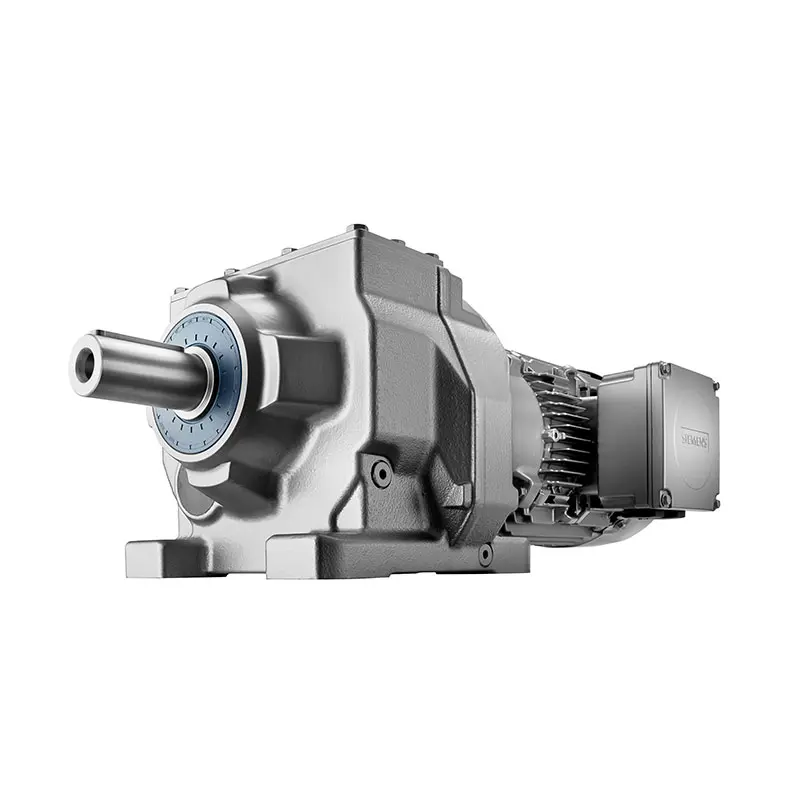 SIEMENS Helical Gearmotor Low Voltage
 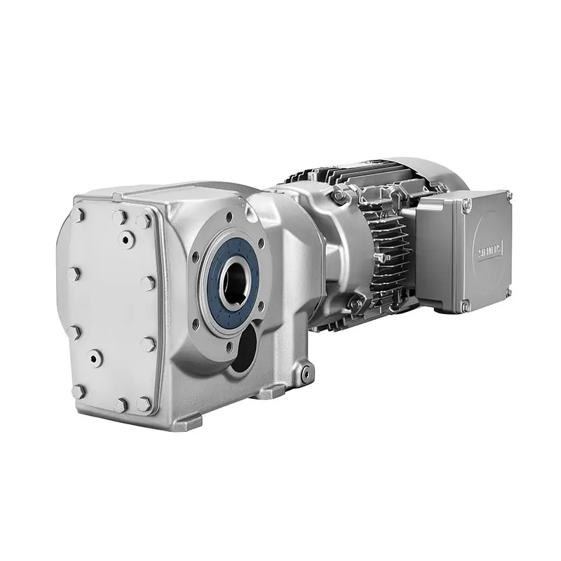 SIEMENS Bevel Helical Gearmotor
 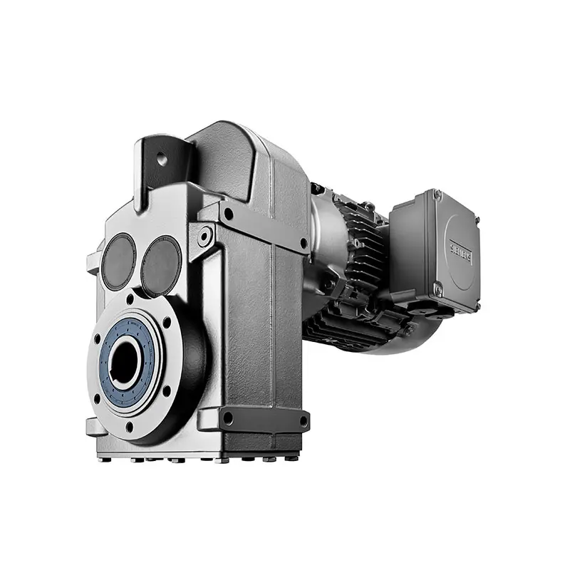 SIEMENS Parallel Shaft Gearmotor
 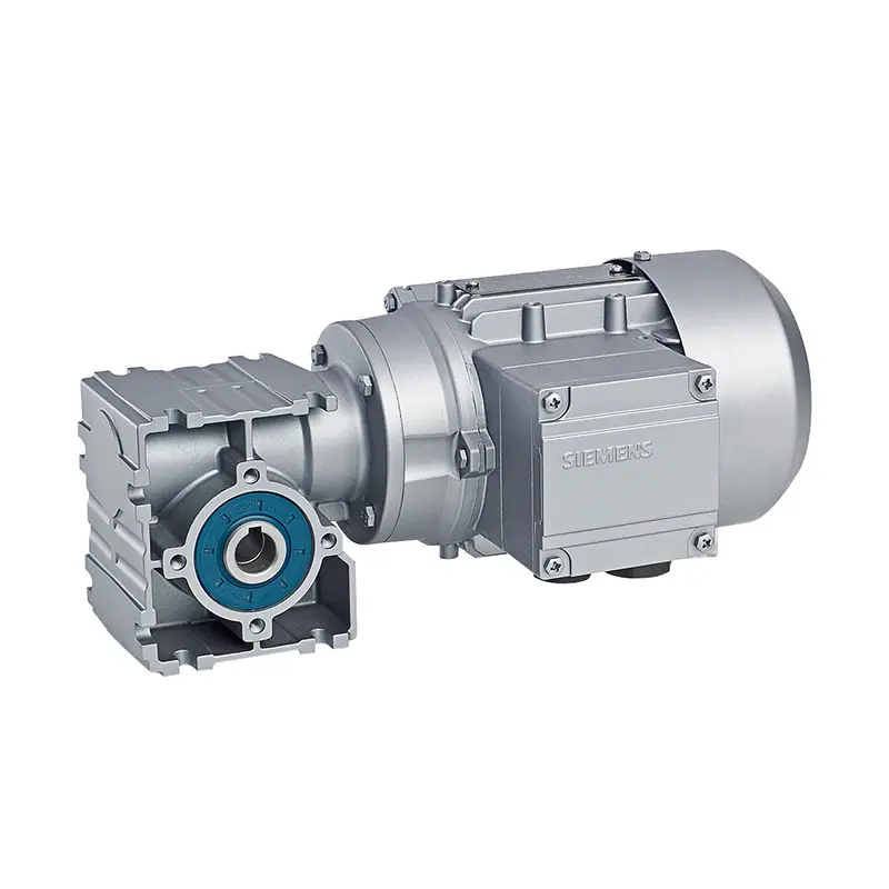 SIEMENS Worm Gearmotor Low Voltage
 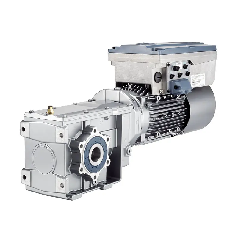 SIEMENS With Servo Motor Gearmotor
 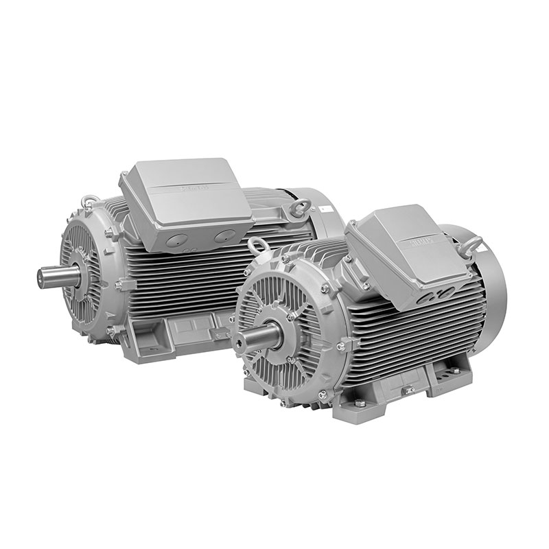 SIEMENS Low Voltage Motor Low Voltage
 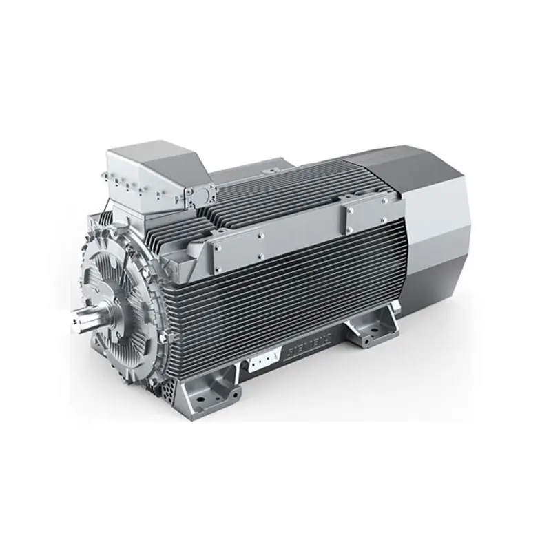 SIEMENS High Voltage Motor Low Voltage
  SIEMENS Marine Motor Low Voltage
 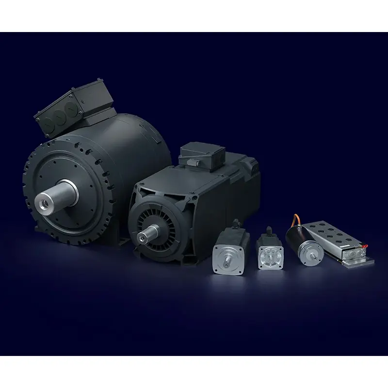 SIEMENS Servo Motor Low Voltage
 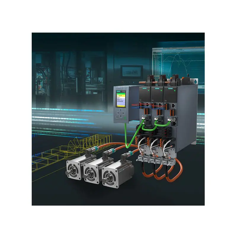 SIEMENS SINAMICS S210 Low Voltage
 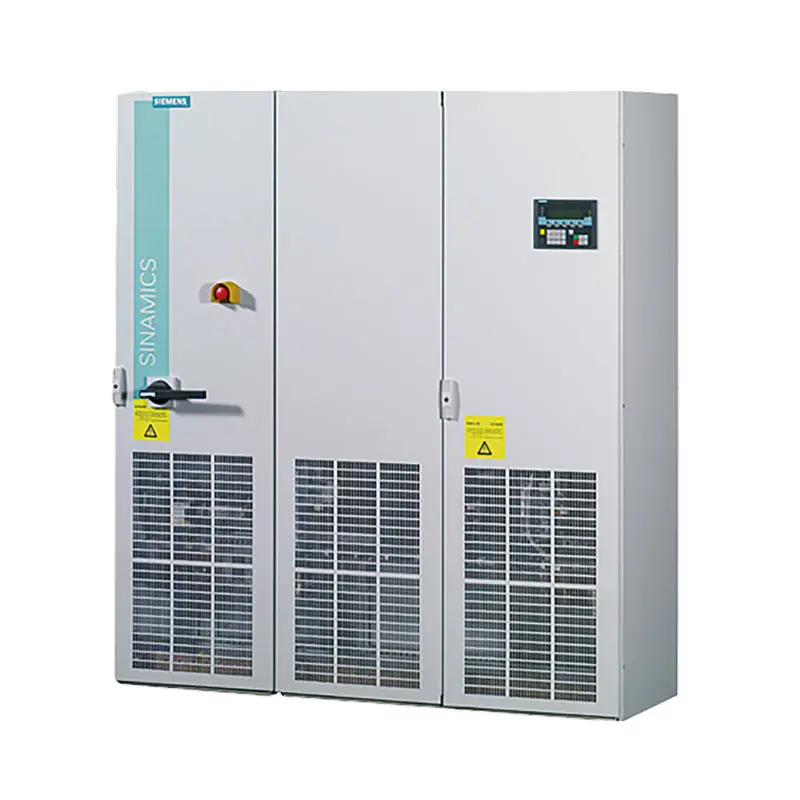 SIEMENS SINAMICS S150 Low Voltage
 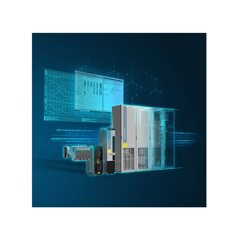 SIEMENS SINAMICS S120 Low Voltage
 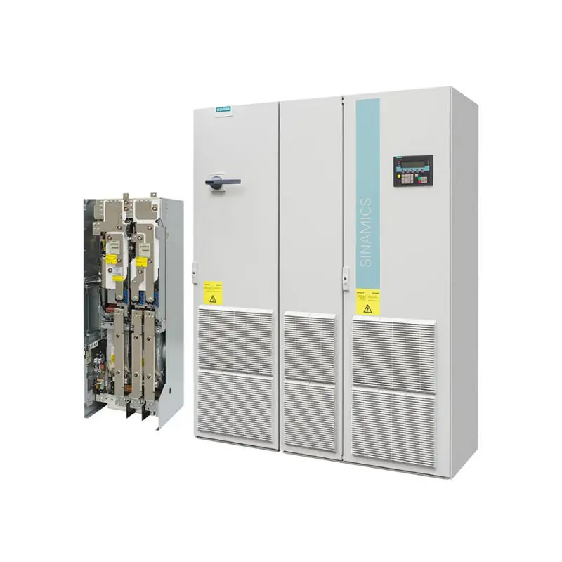 SIEMENS SINAMICS G130/G150
 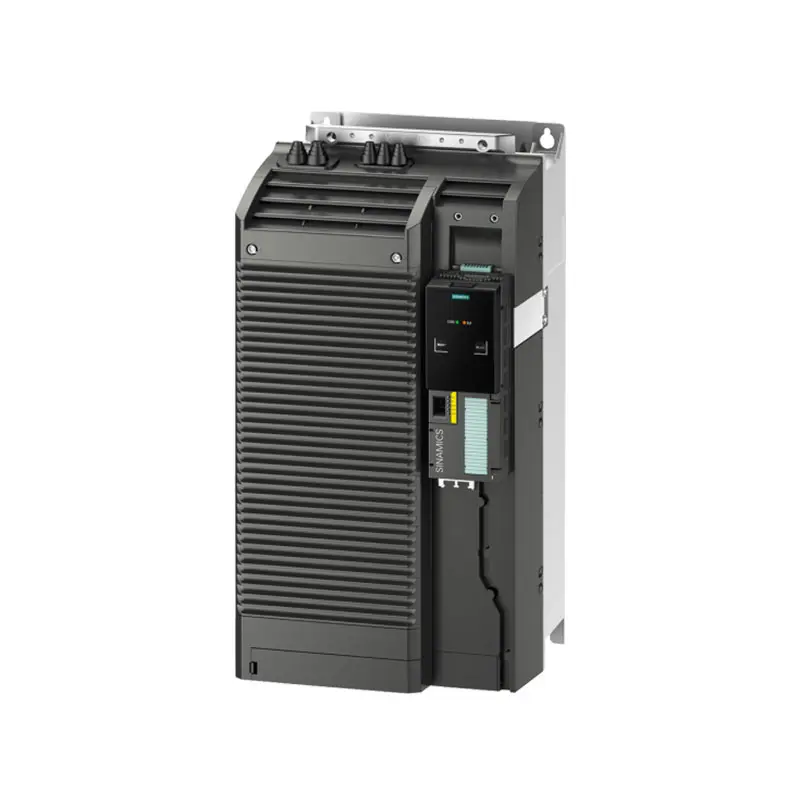 SIEMENS SINAMICS G120 Low Voltage
 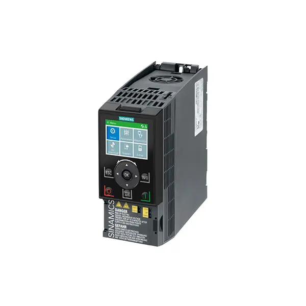 SIEMENS SINAMICS G120C Low Voltage
 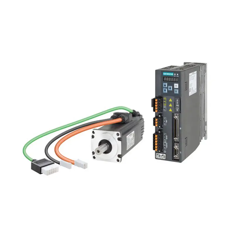 SIEMENS SINAMICS V90
 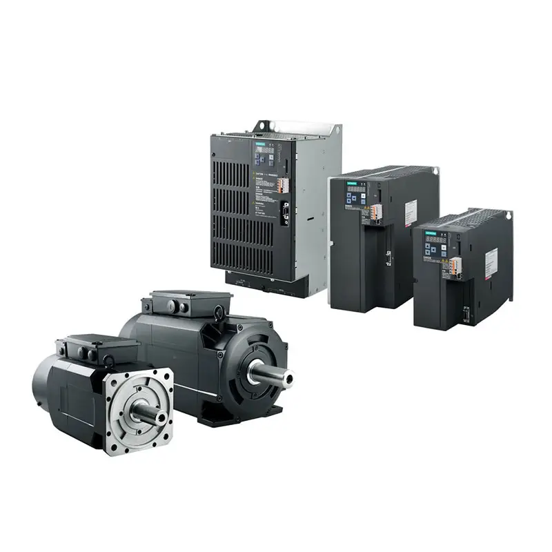 SIEMENS SINAMICS V70 Low Voltage
 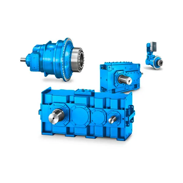 FLENDER Gear Unit
 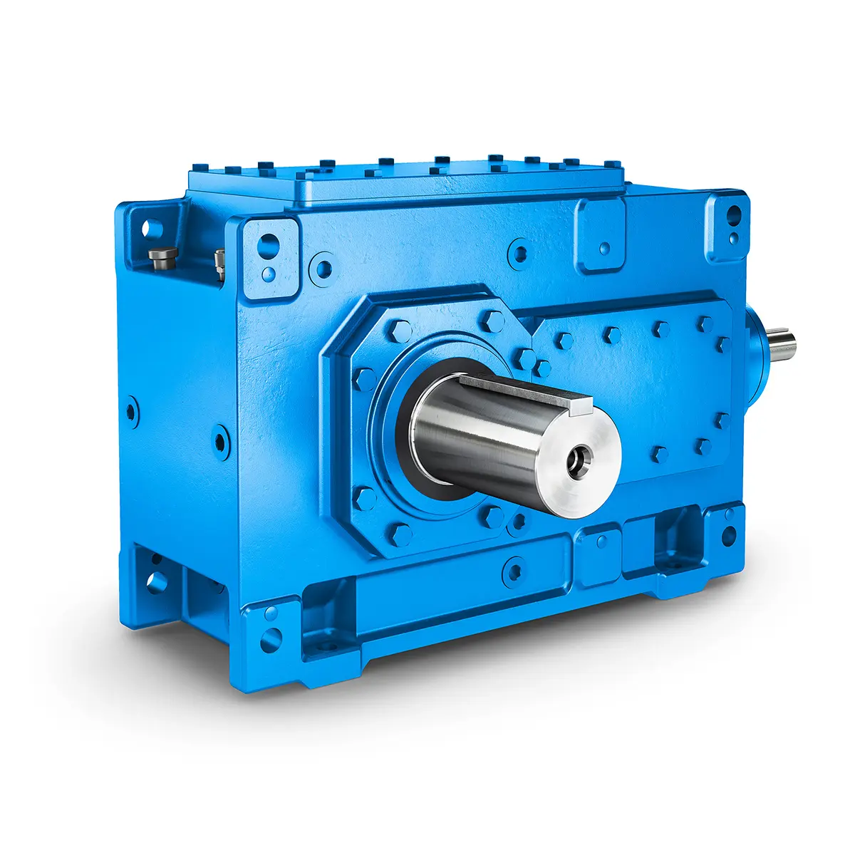 FLENDER Helical Gear Unit
 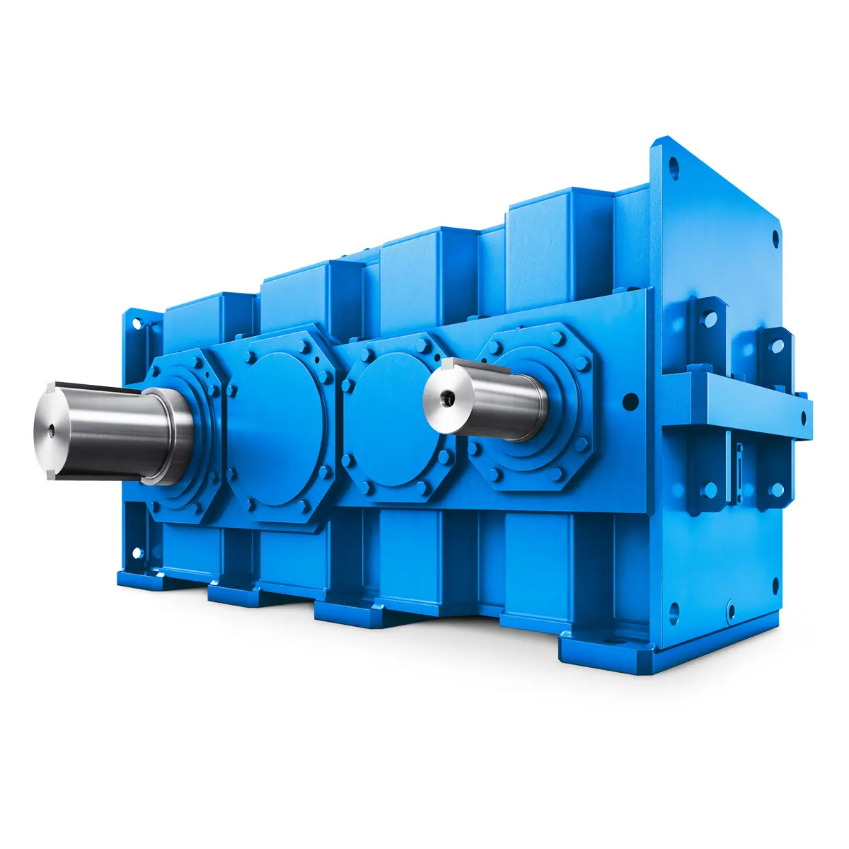 Flender gear units for lifting and luffing gears
 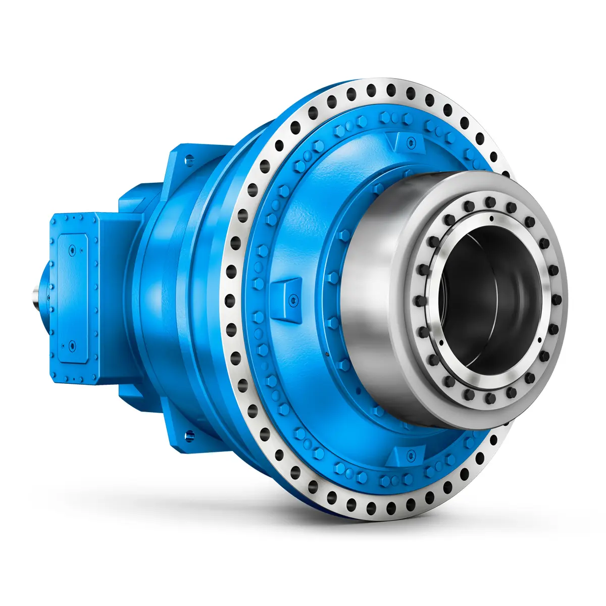 FLENDER Gear Unit gearunit gearbox
 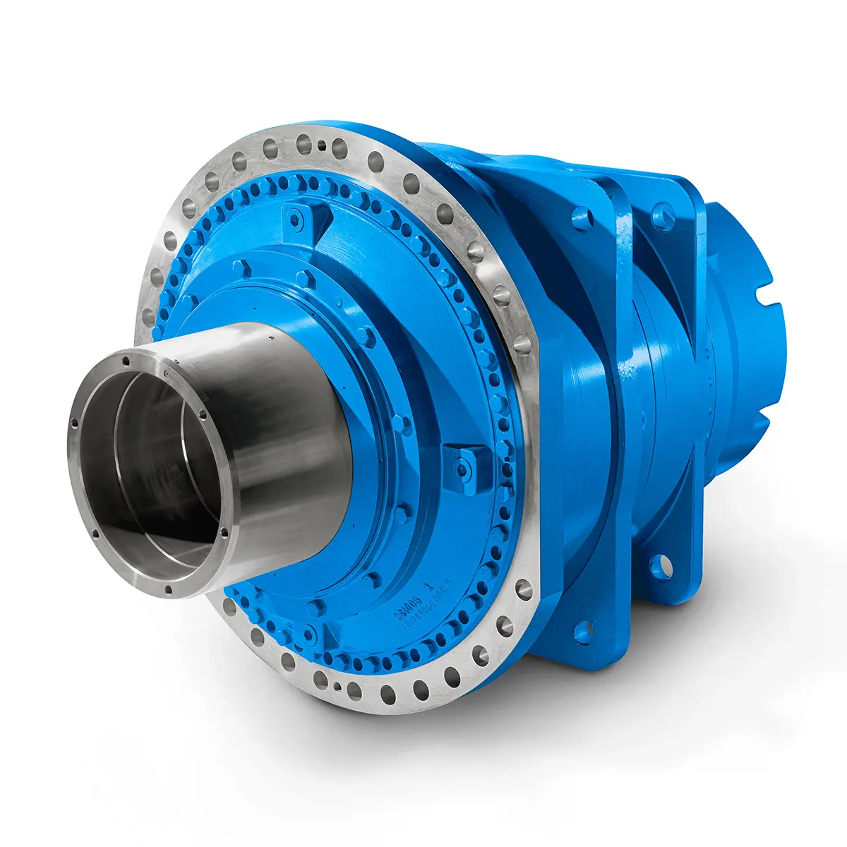 Optimal Drive Solution For Maximum Performance
 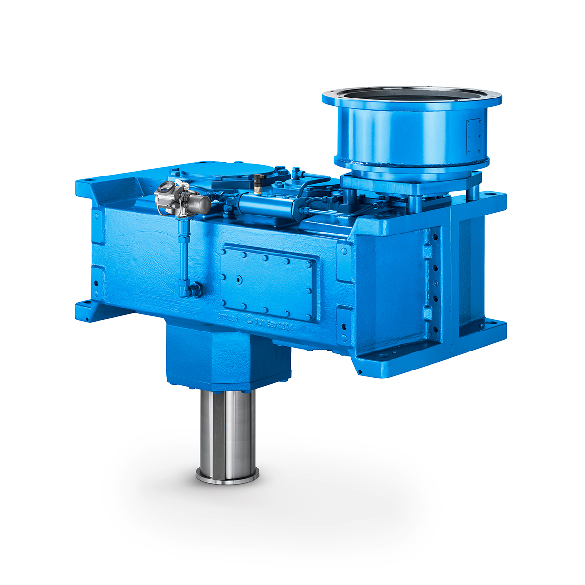 Strongly operating against biodegradable constituents
 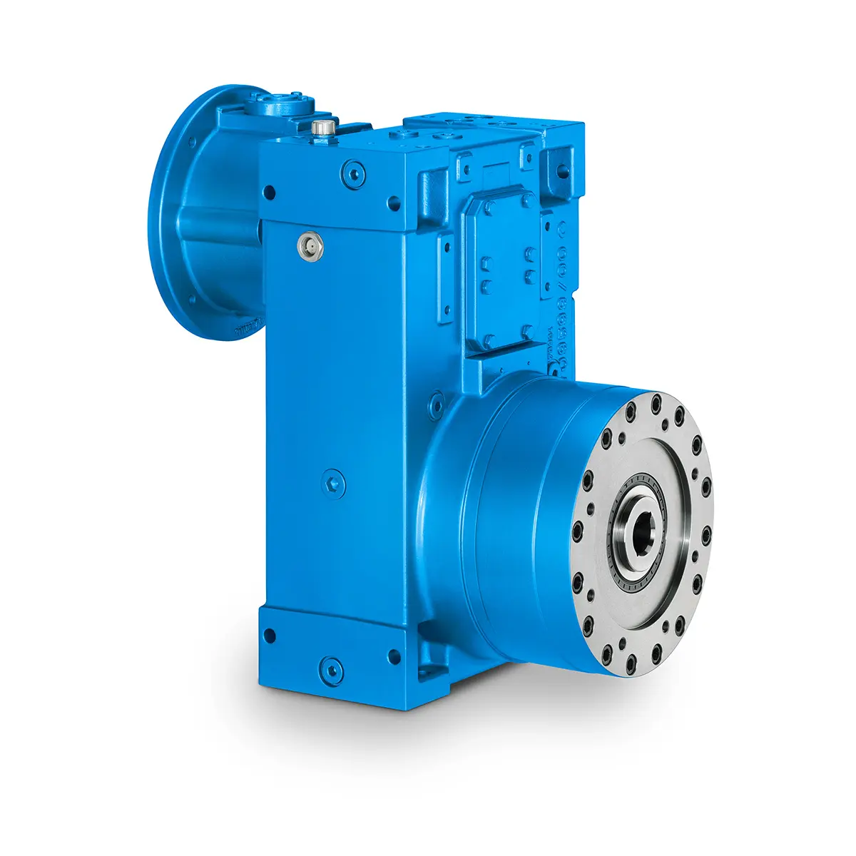 SINGLE SCREW Special industry dedicated gearunit gearbox
 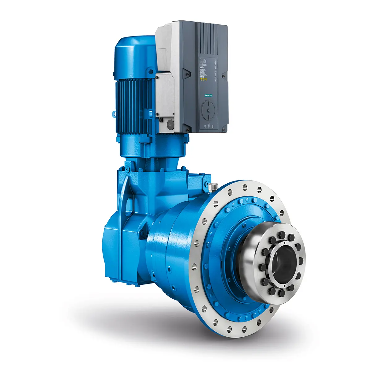 Playmaker In The Premium League
 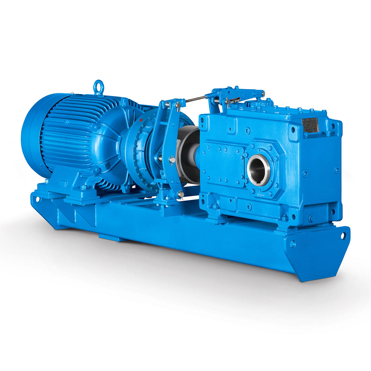 Conveyor belts gearunit gearbox
 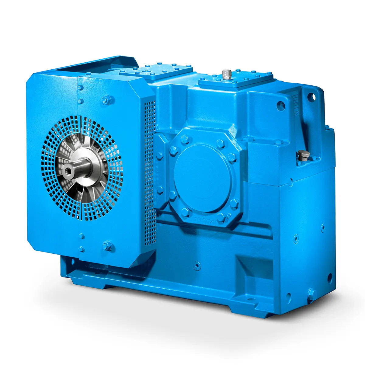 Paper And Pulp Preparation Sections
 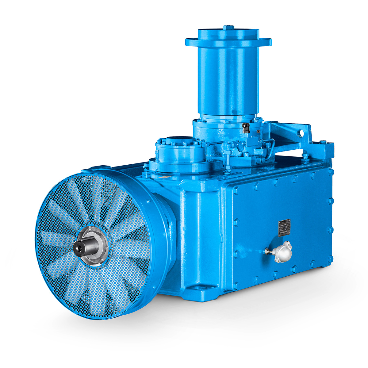 Operational Reliability Even In Case Of The Highest Ventilation Forces
 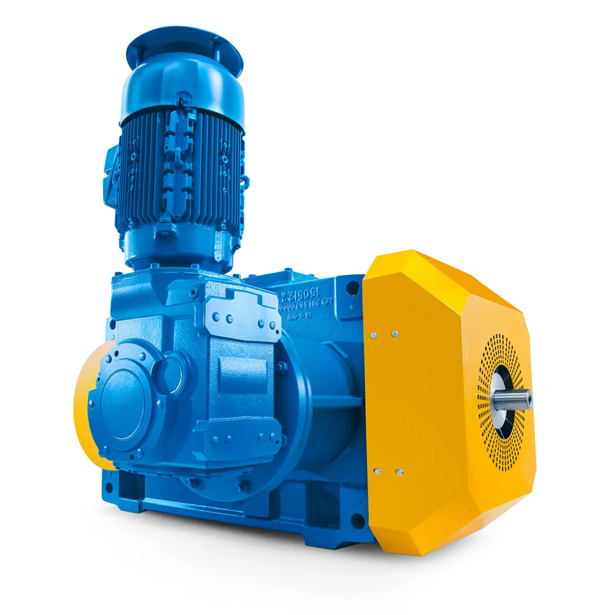 Reliable Gear Units For High Performance Vertical Conveyors 59/200
 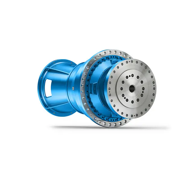 Maximum power density – PLANUREX 3 L individual drives for your sugar cane mill
 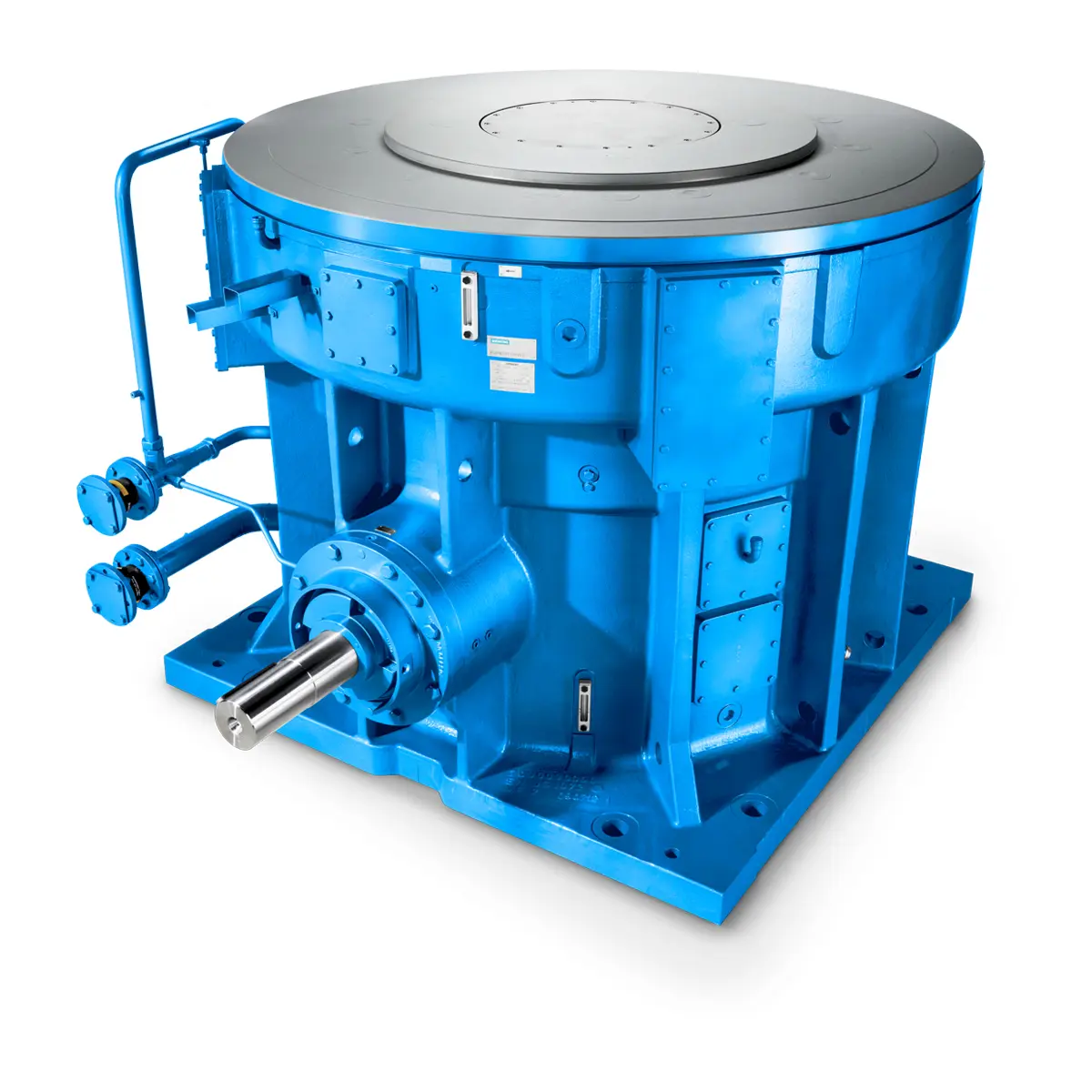 The proven all rounder gearunit gearbox
 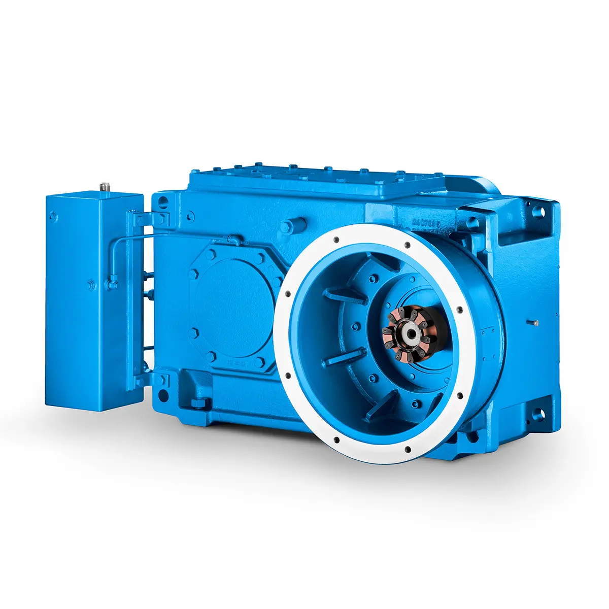 Stirs and stirs and stirs gearunit gearbox
 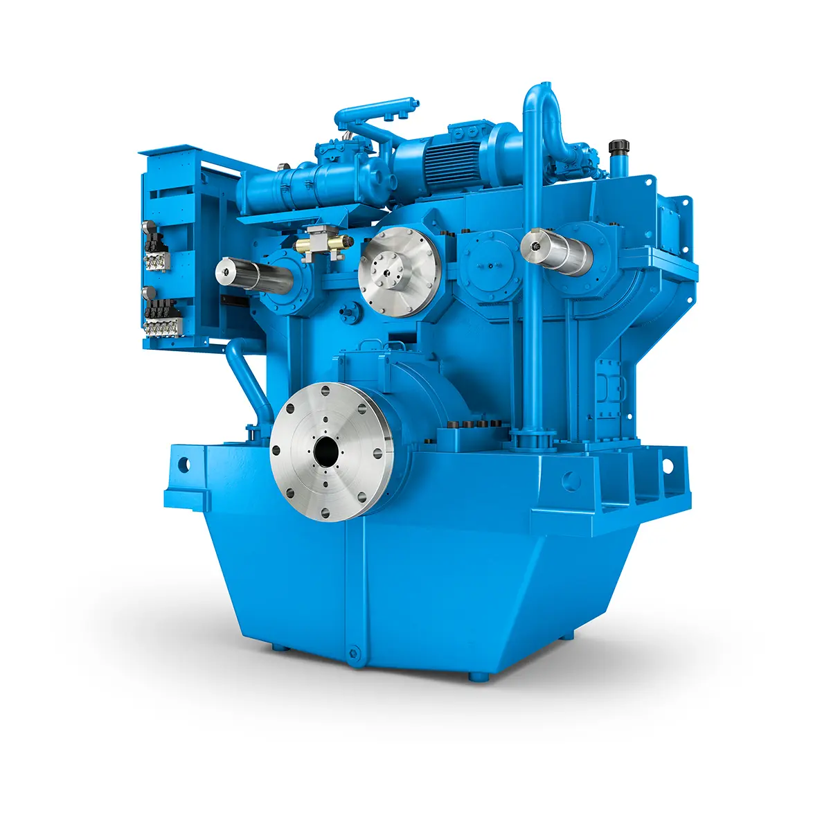 Flexibility on Board gearunit gearbox
 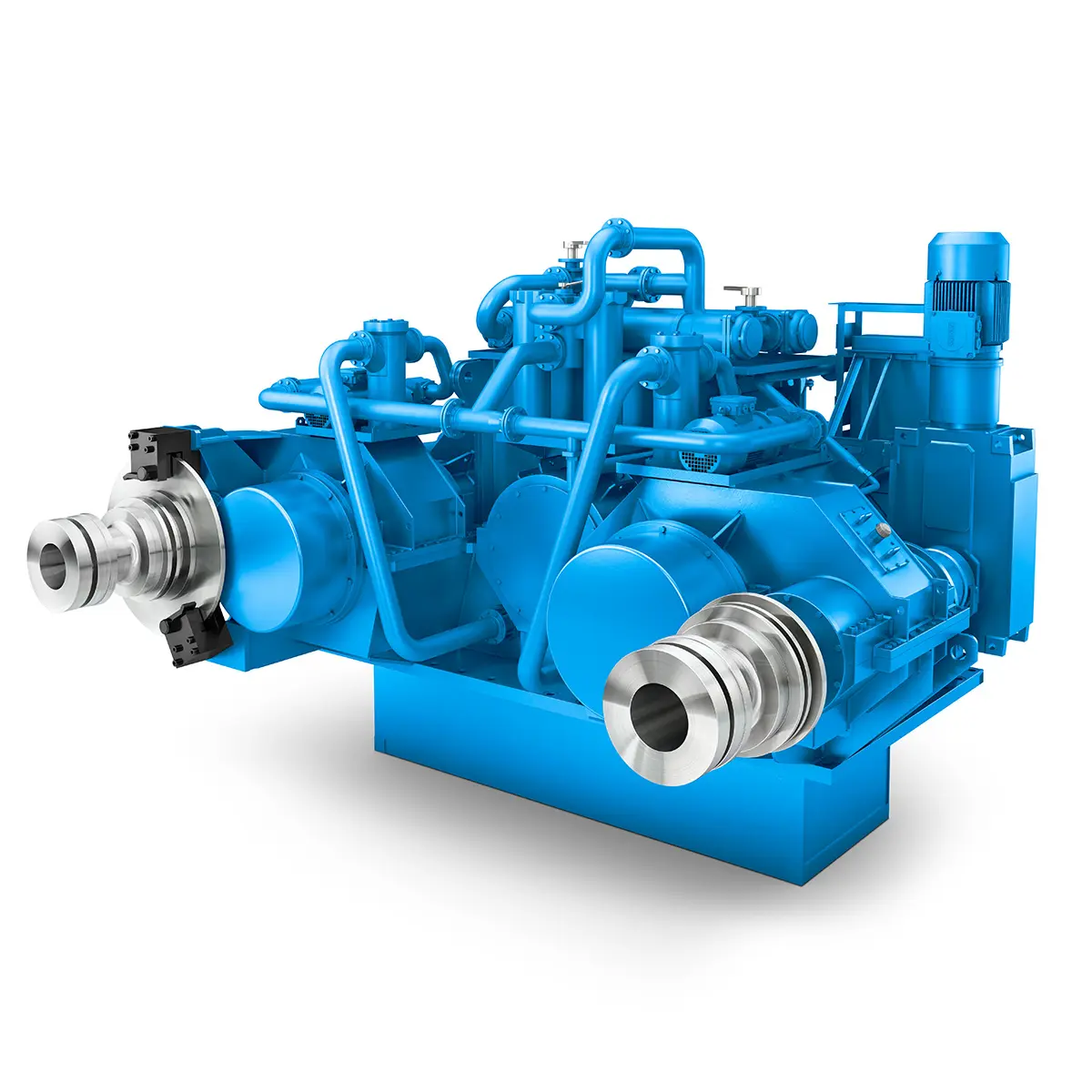 The right gearbox for all Multi-Engine Ships
  Reliable Power Generation on board
 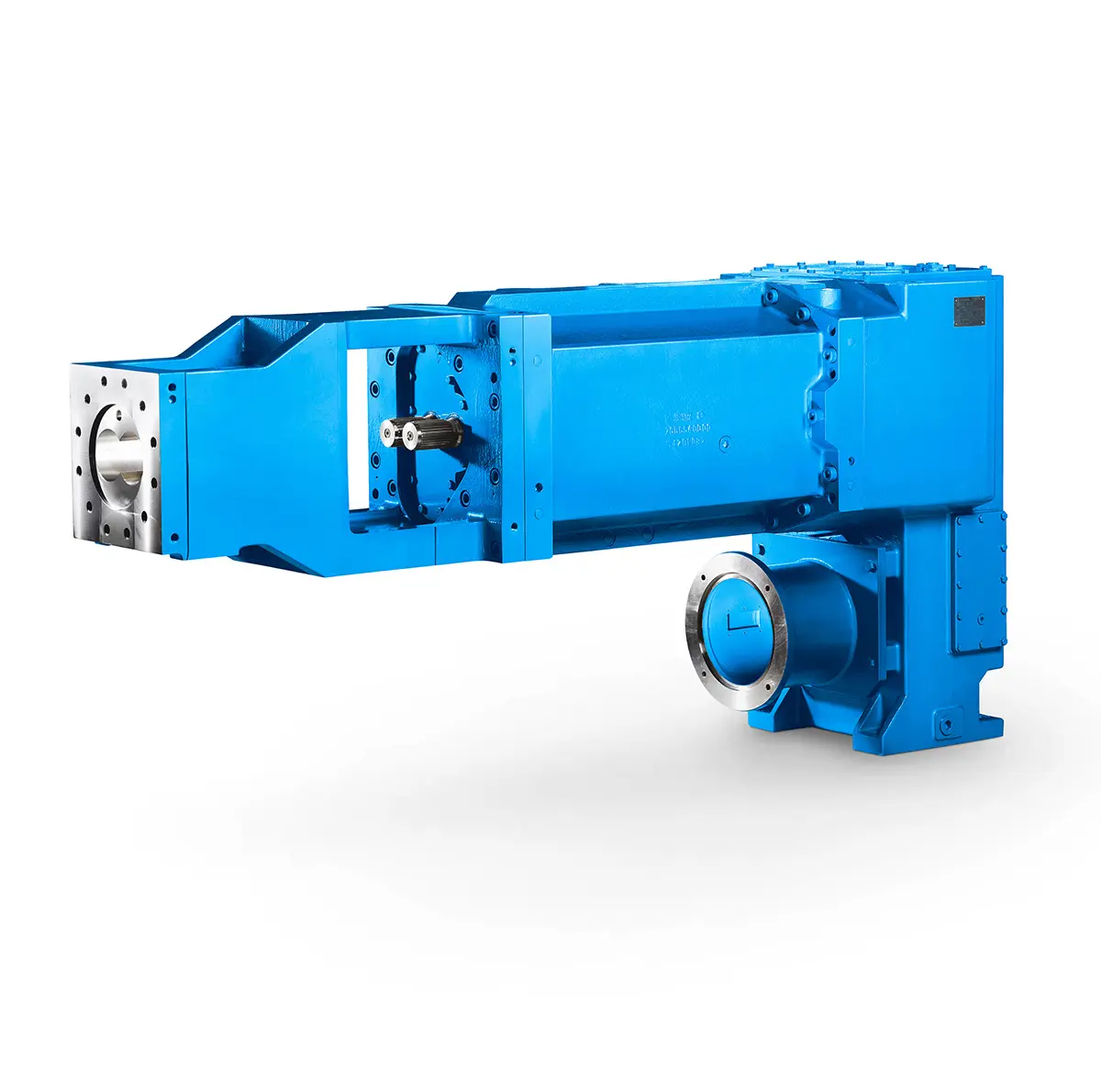 Maximum performance level, fast deliverable
 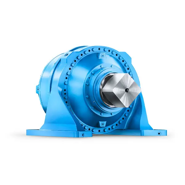 Efficient and compact – FLENDER Gear Units for Sugar Mills
 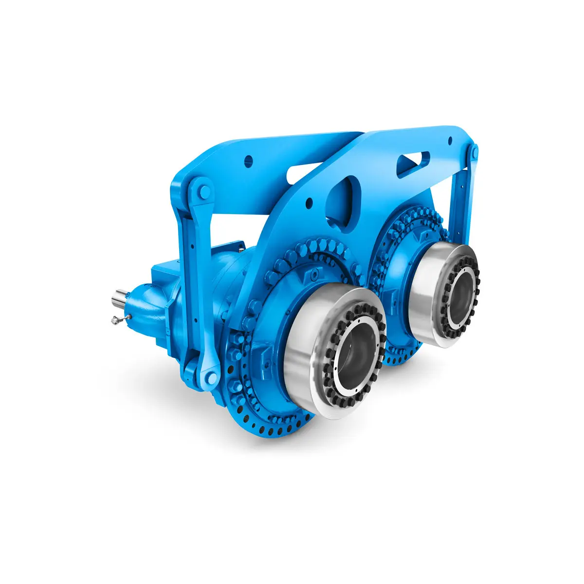 Extremely strong. Extremely compact. Extremely stressable.
 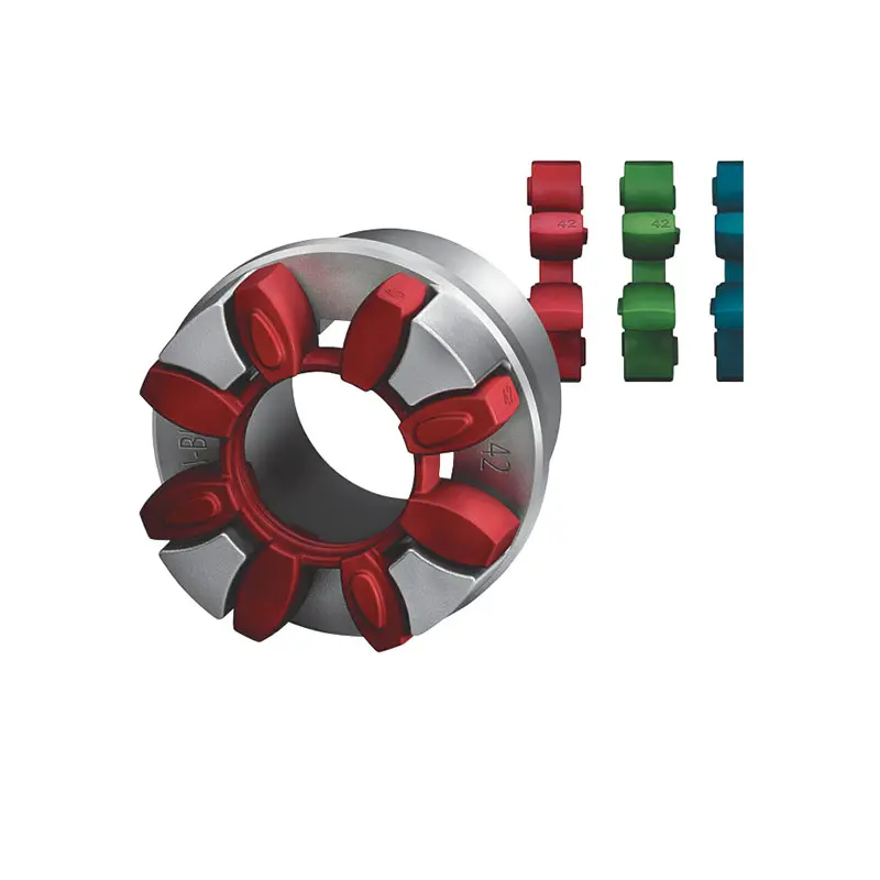 FLENDER Coupling
 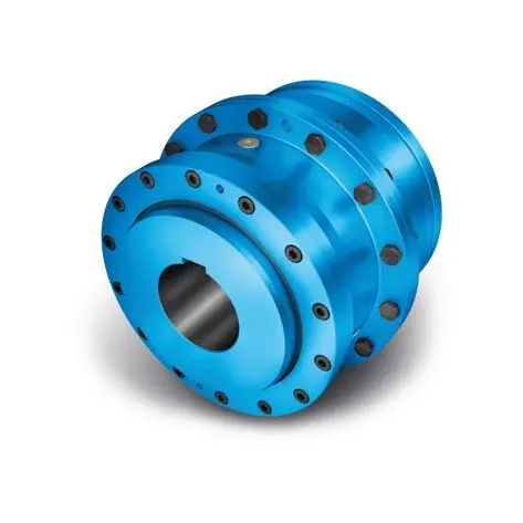 ZAPEX ZW Torsionally Rigid Gear Coupling
 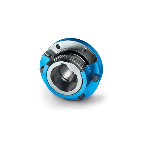 ZAPEX ZN Torsionally Rigid Gear Coupling
 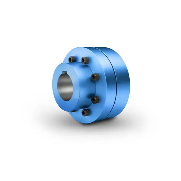 N-EUPEX Flexible high performance Coupling
 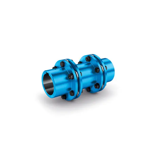 N-ARPEX Torsionally Rigid All-Steel Coupling
 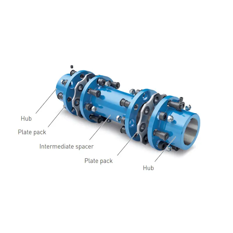 ARPEX Torsionally Rigid All-Steel Coupling Spare and Parts
 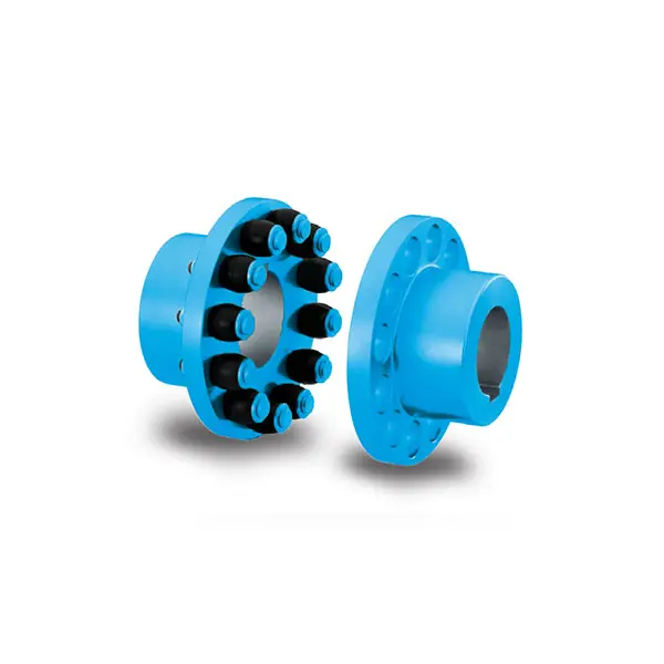 RUPEX Flexible high performance Coupling
 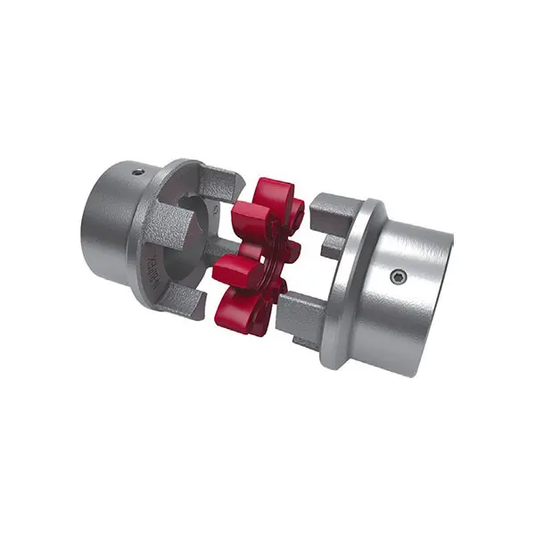 N BIPEX Flexible high performance coupling
 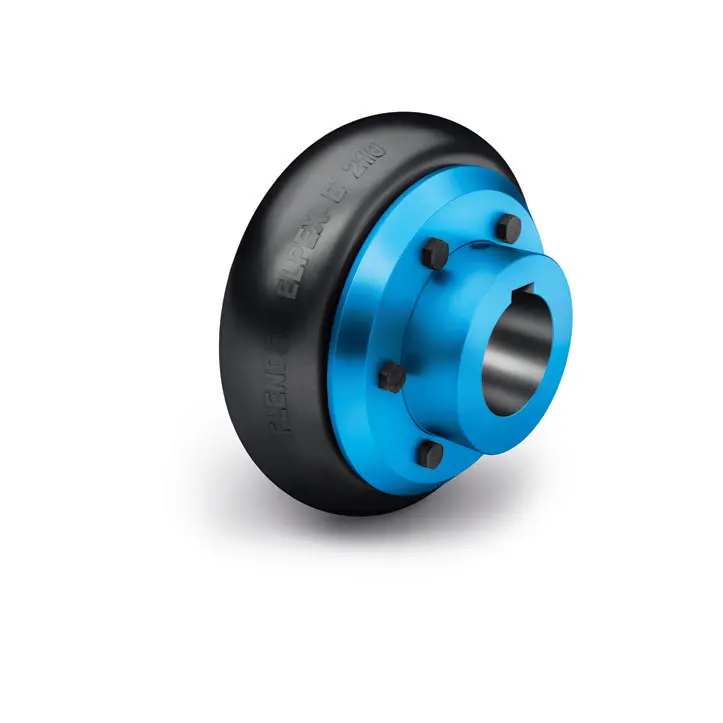 ELPEX B Highly Flexible Coupling
 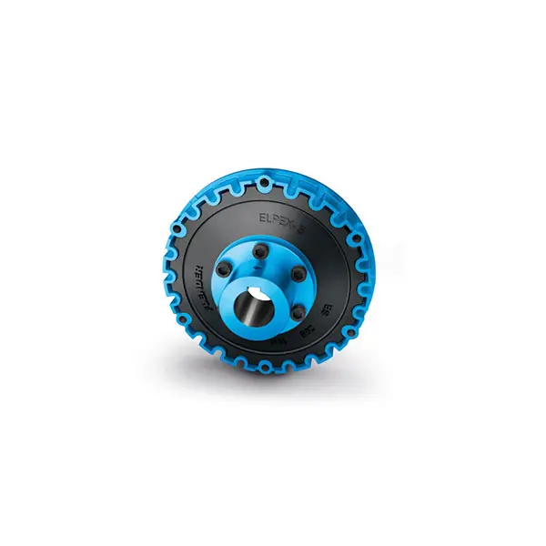 ELPEX S Highly Flexible Coupling high performance
 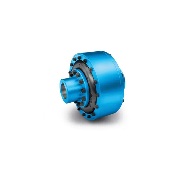 ELPEX Highly Flexible Coupling high performance
 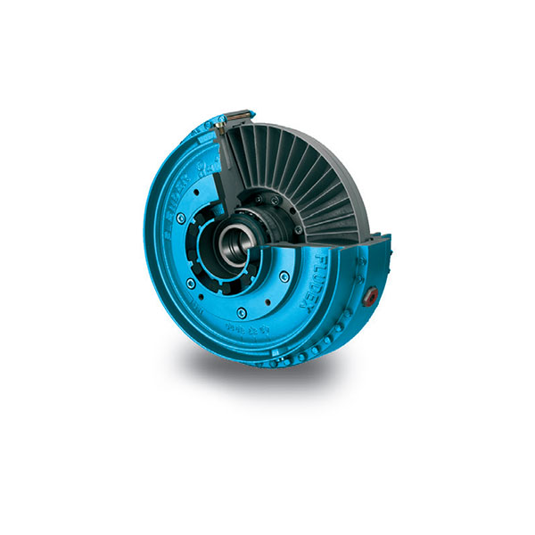 FLUDEX Fluid Coupling high performance
 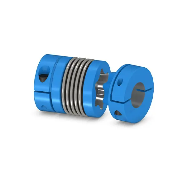 SIPEX Backlash free Coupling high performance
 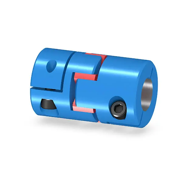 BIPEX S Backlash free Coupling high performance
 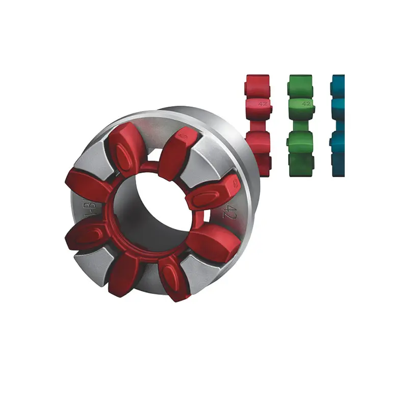 FLENDER Coupling Spare Parts high performance
 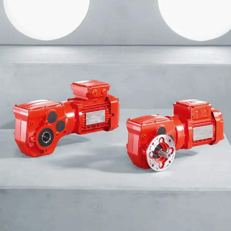 SEW Gearmotor
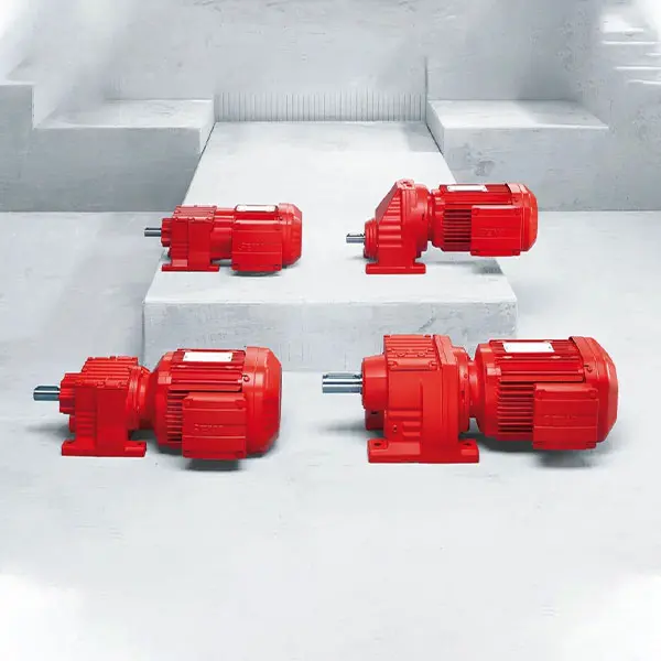 R Series Helical Gearmotor low voltage
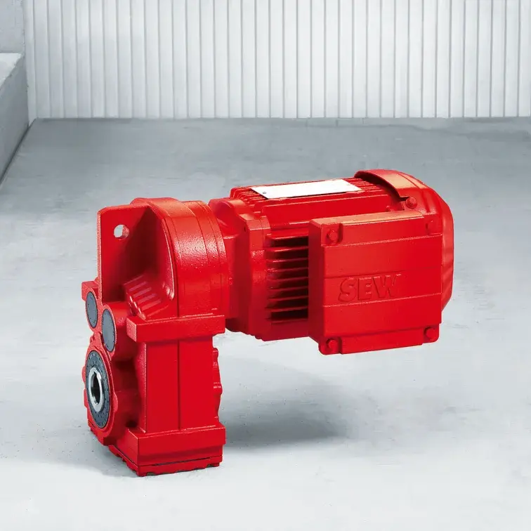 F Series Parallel Shaft Gearmotor low voltage
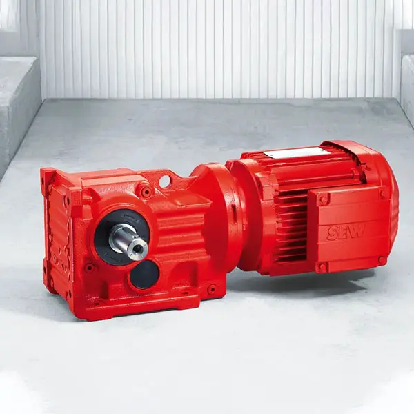 K Series Helical Bevel Gearmotor low voltage
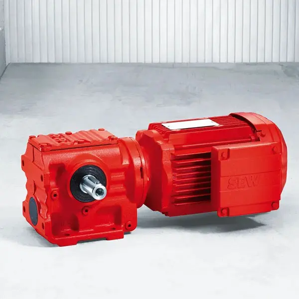 S Series Helical Worm Gearmotor low voltage
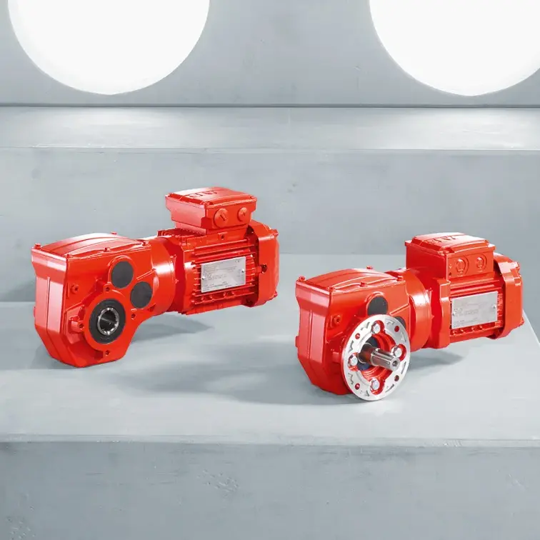 W Series SPIROPLAN® Right Angle Gearmotor