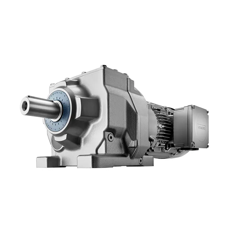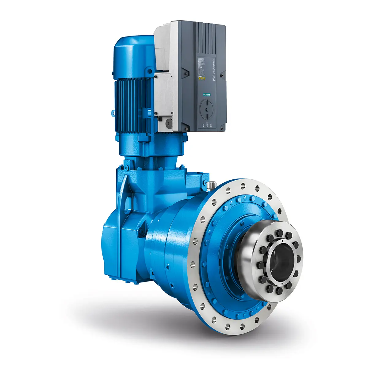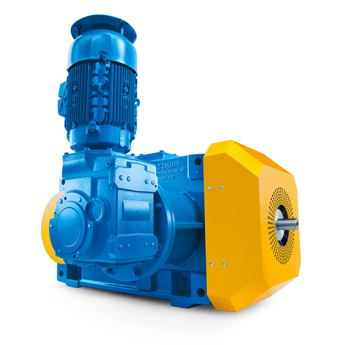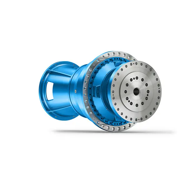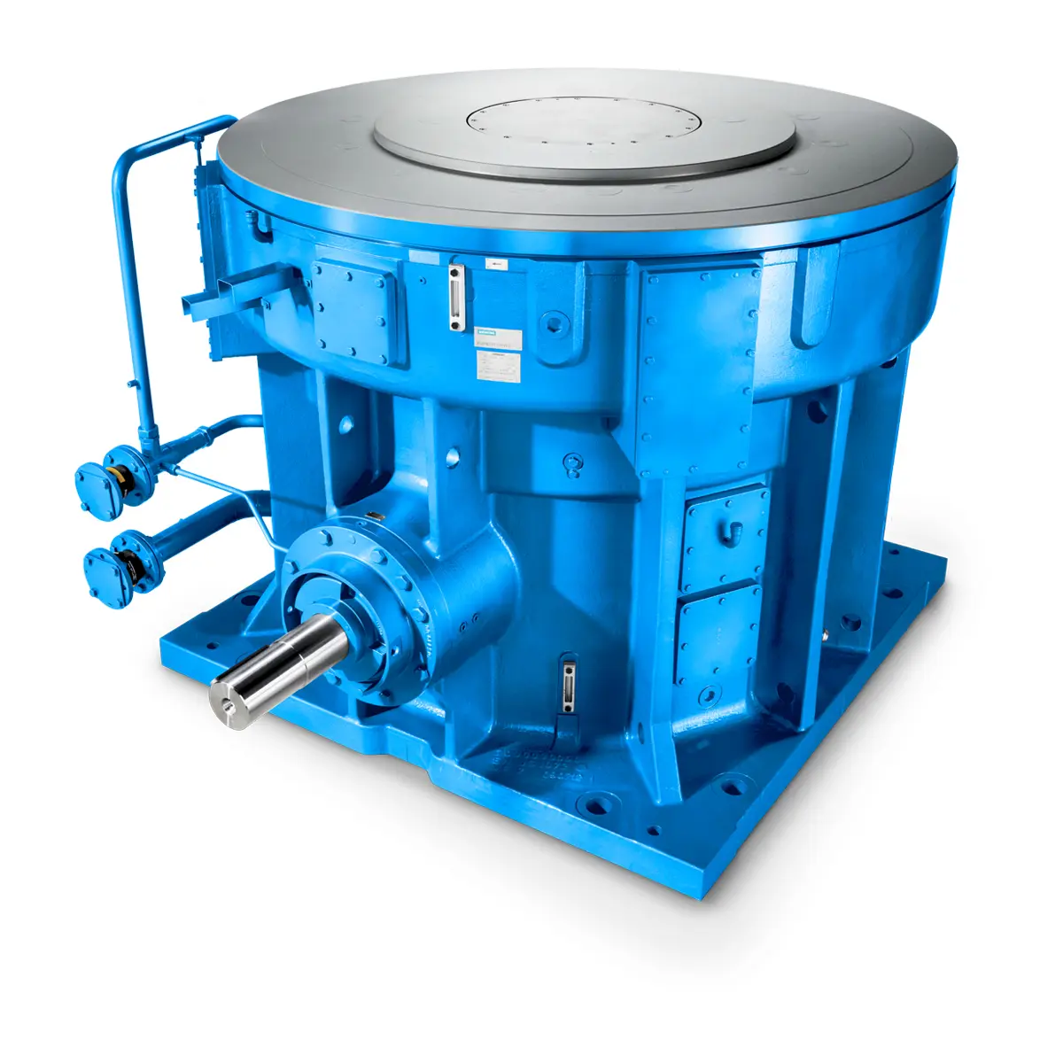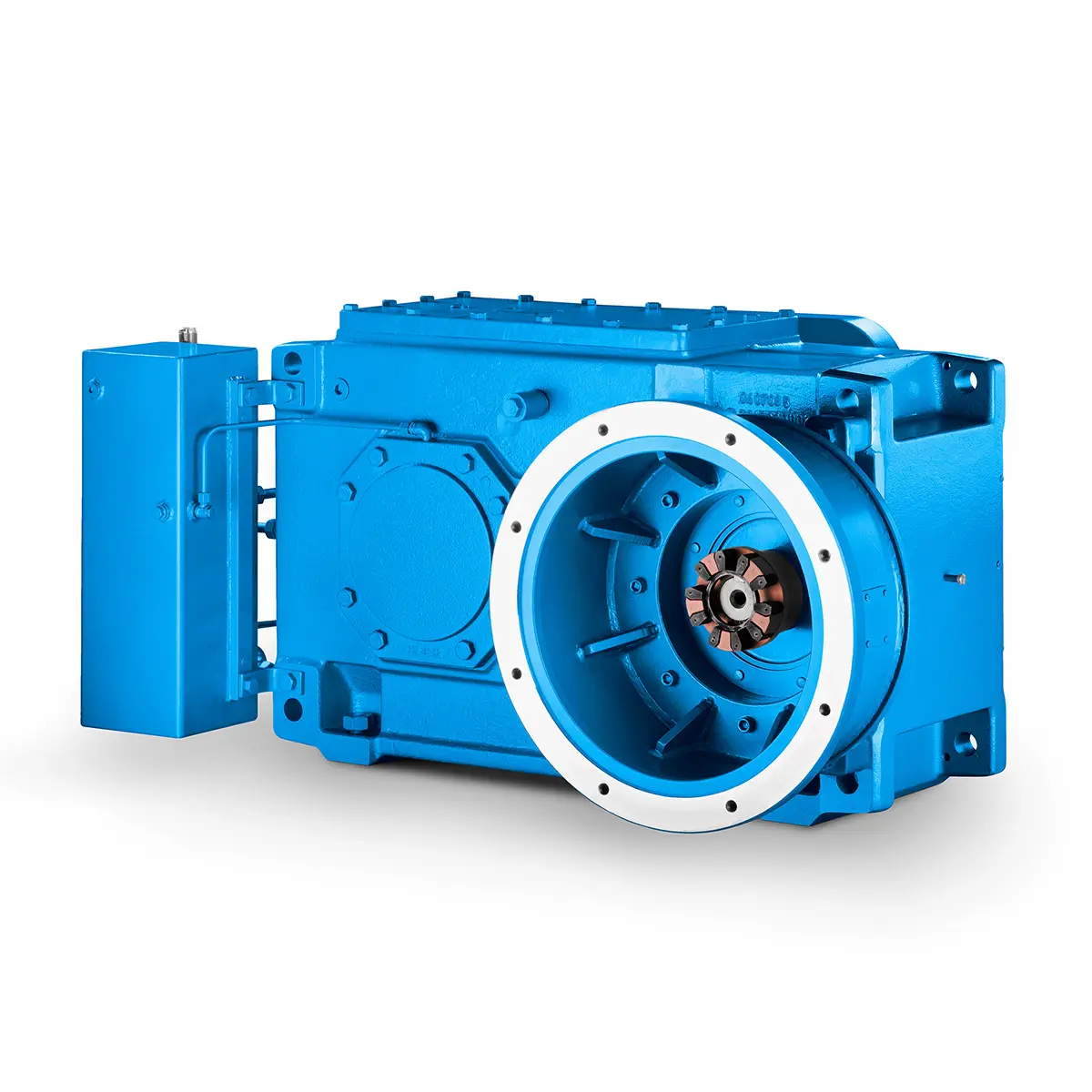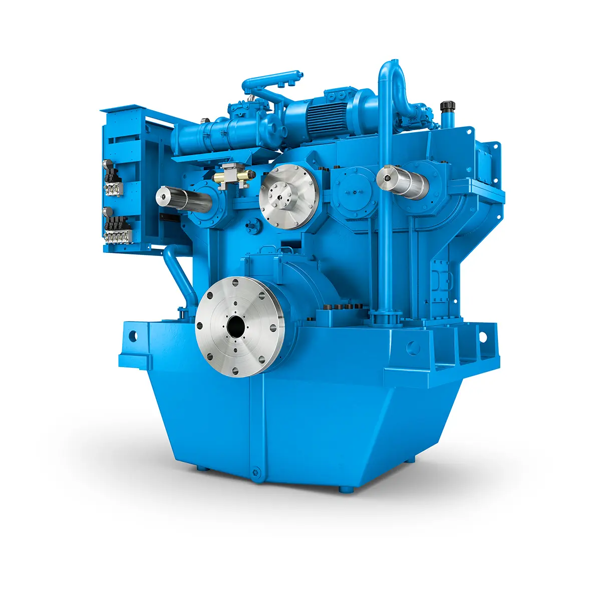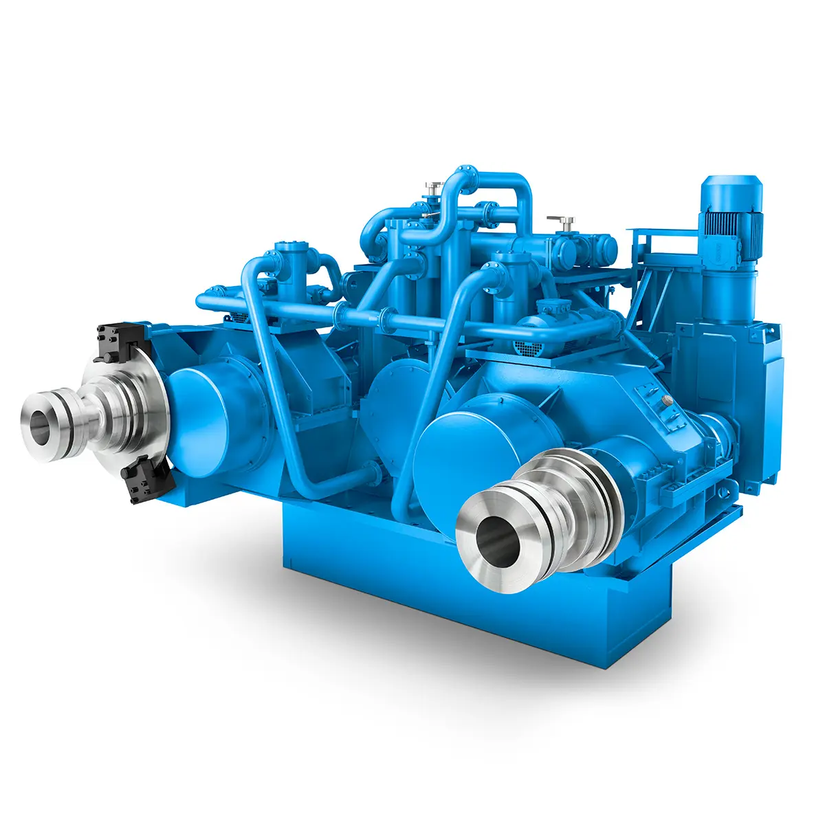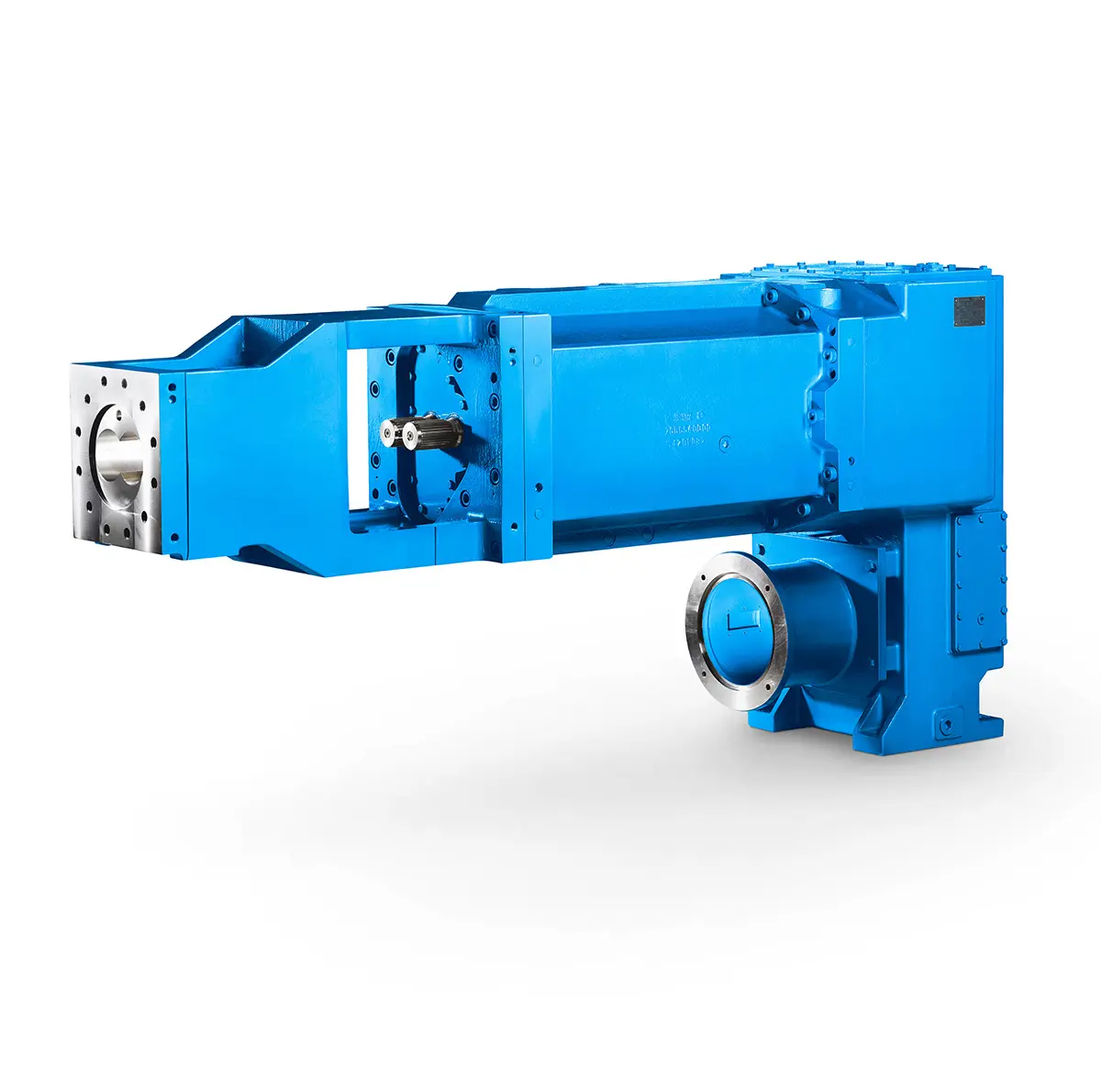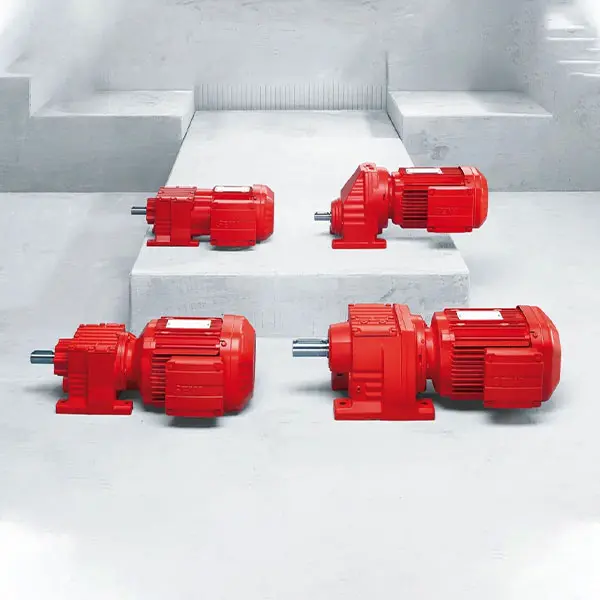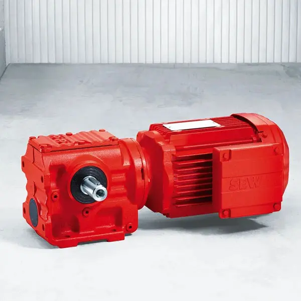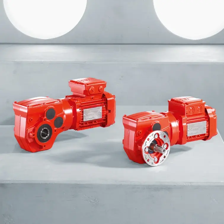
SIEMENS Helical Gearmotor Low Voltage
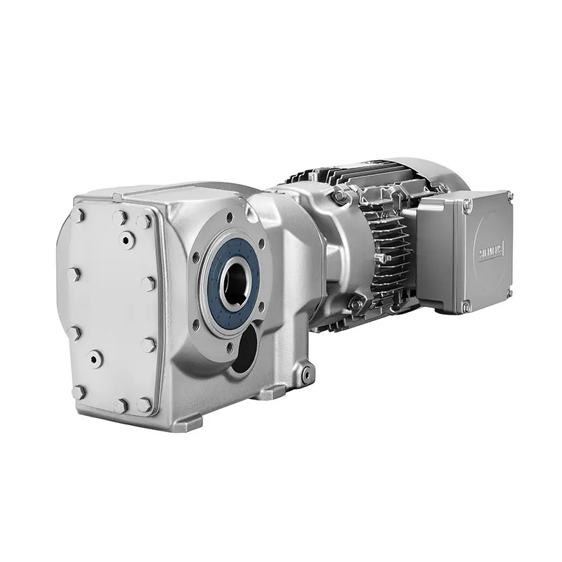
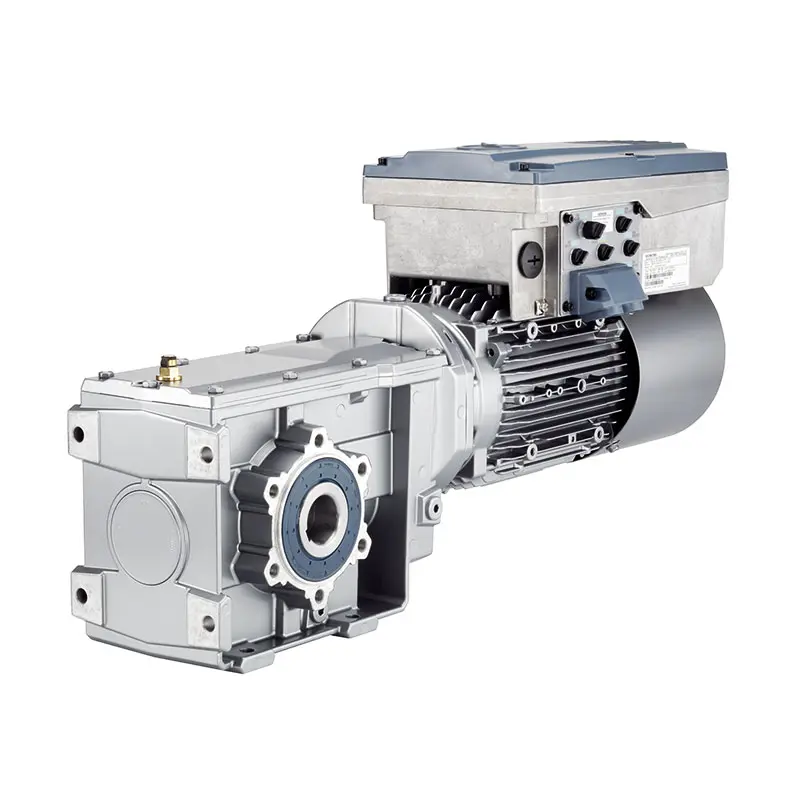
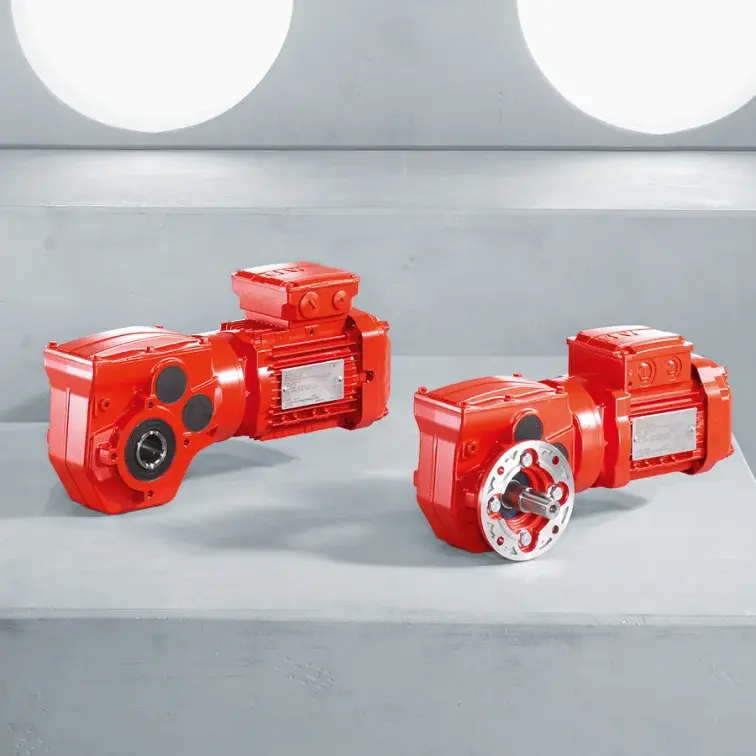
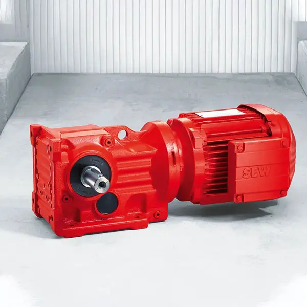
SIEMENS Bevel Helical Gearmotor
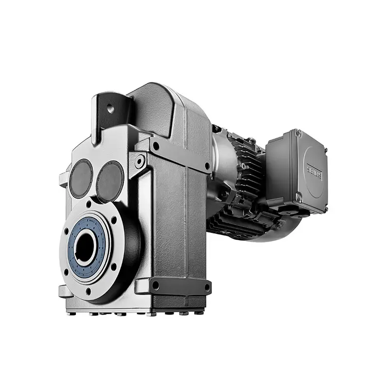
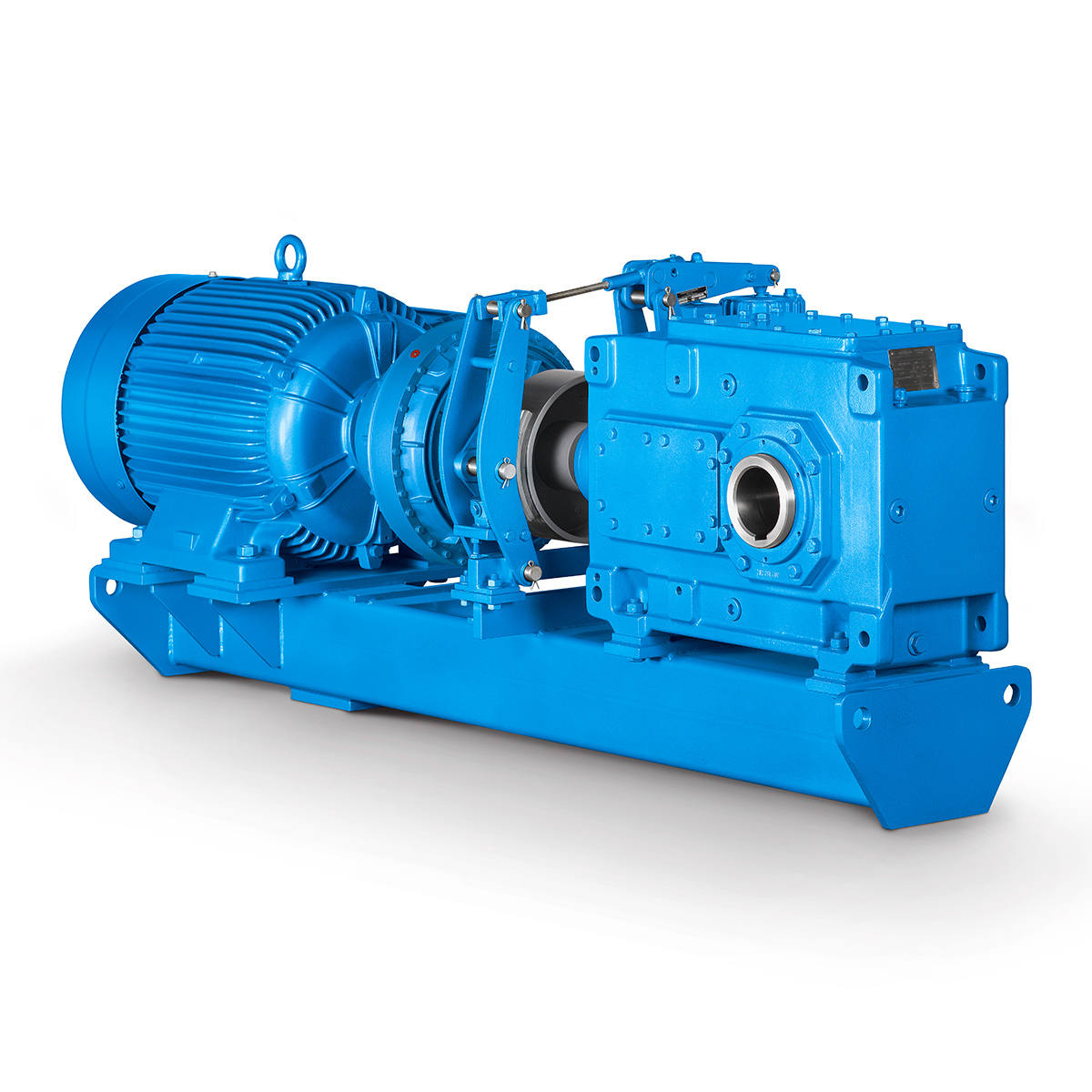
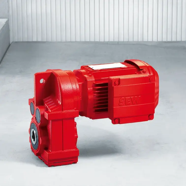
SIEMENS Parallel Shaft Gearmotor
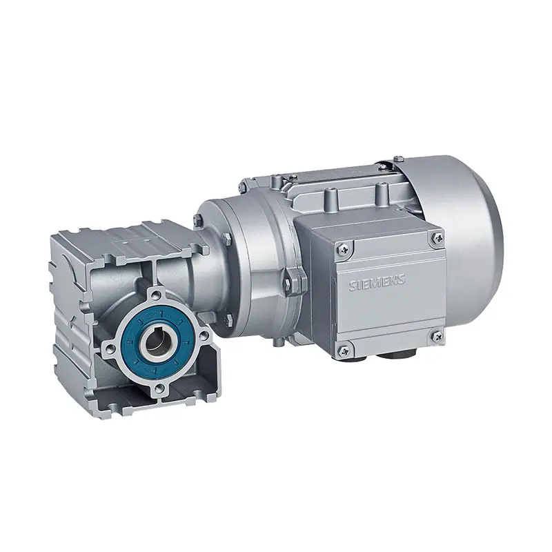
SIEMENS Worm Gearmotor Low Voltage
SIEMENS With Servo Motor Gearmotor
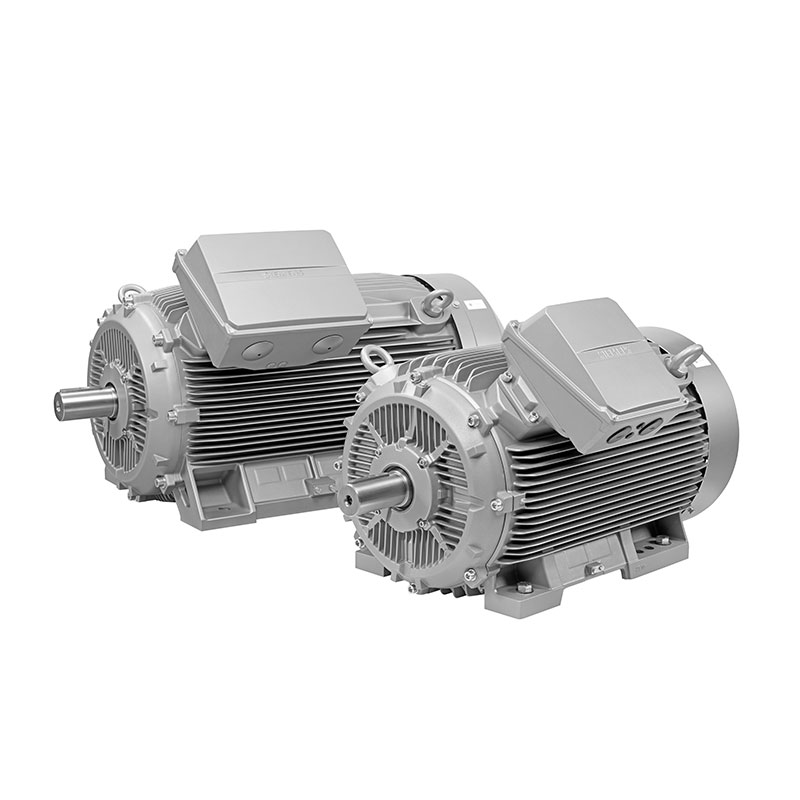
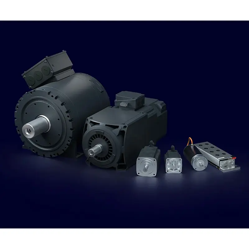
SIEMENS Low Voltage Motor Low Voltage
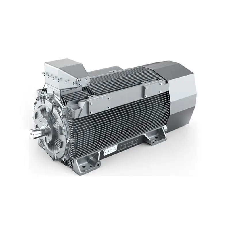
SIEMENS High Voltage Motor Low Voltage
SIEMENS Marine Motor Low Voltage
SIEMENS Servo Motor Low Voltage
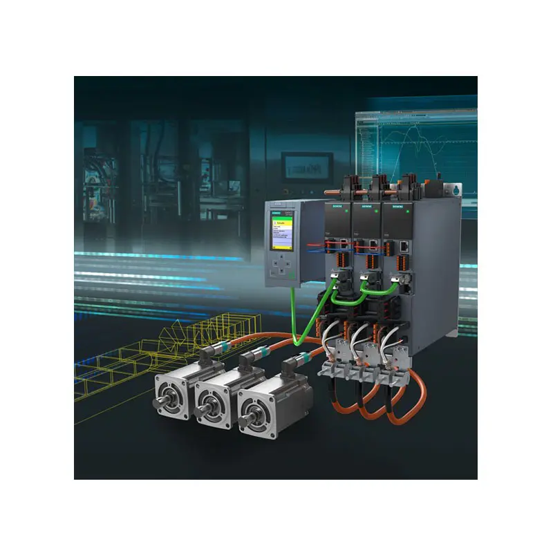
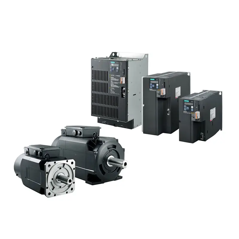
SIEMENS SINAMICS S210 Low Voltage
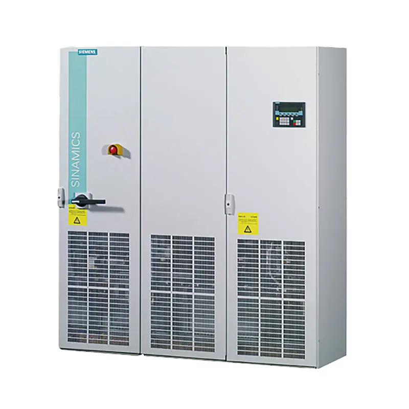
SIEMENS SINAMICS S150 Low Voltage
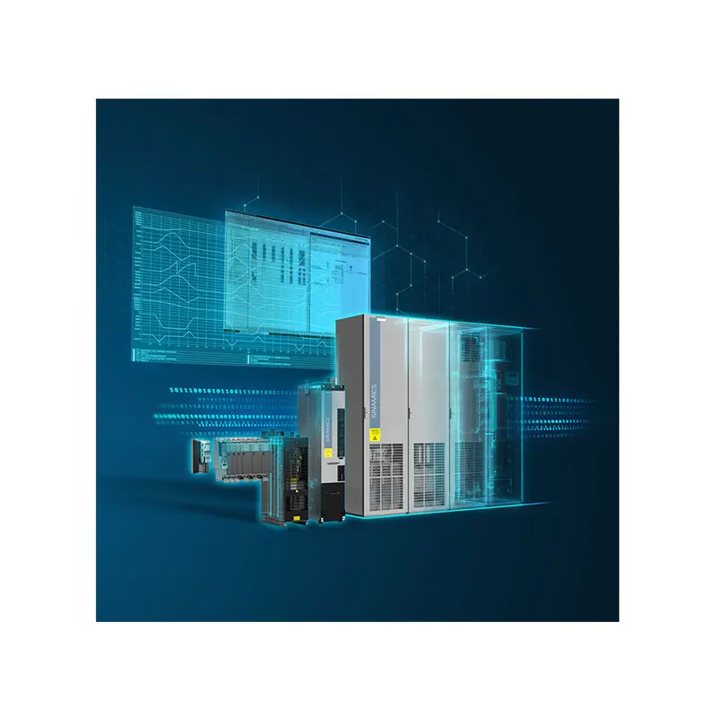
SIEMENS SINAMICS S120 Low Voltage
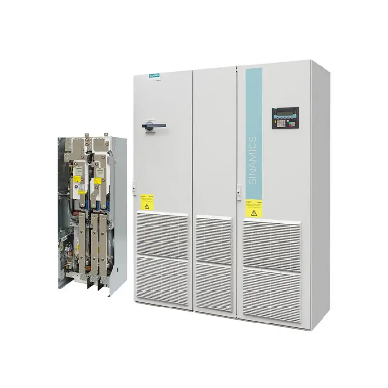
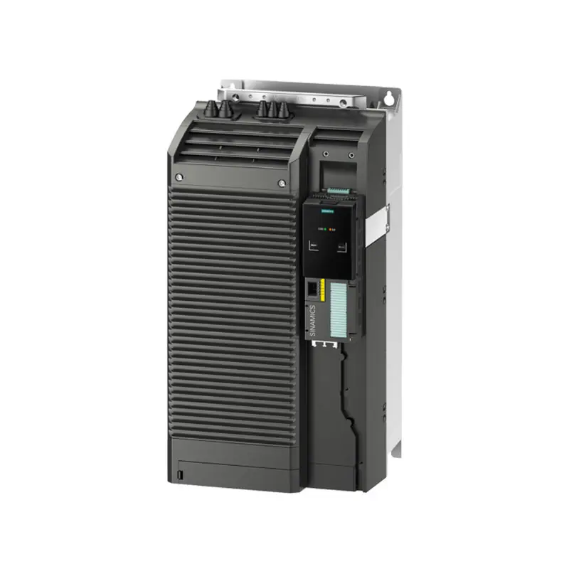
SIEMENS SINAMICS G130/G150
SIEMENS SINAMICS G120 Low Voltage
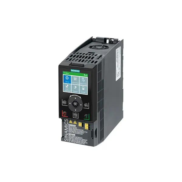
SIEMENS SINAMICS G120C Low Voltage
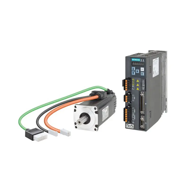
SIEMENS SINAMICS V90
SIEMENS SINAMICS V70 Low Voltage
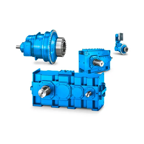
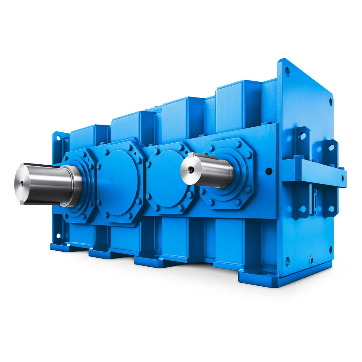
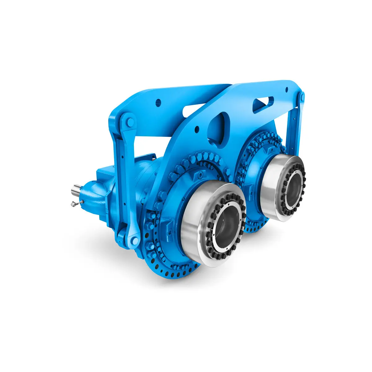
FLENDER Gear Unit
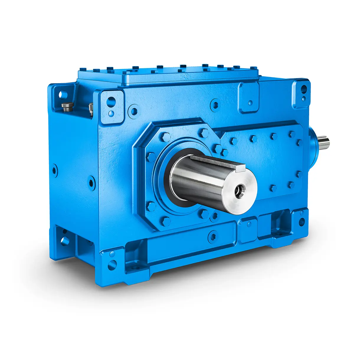
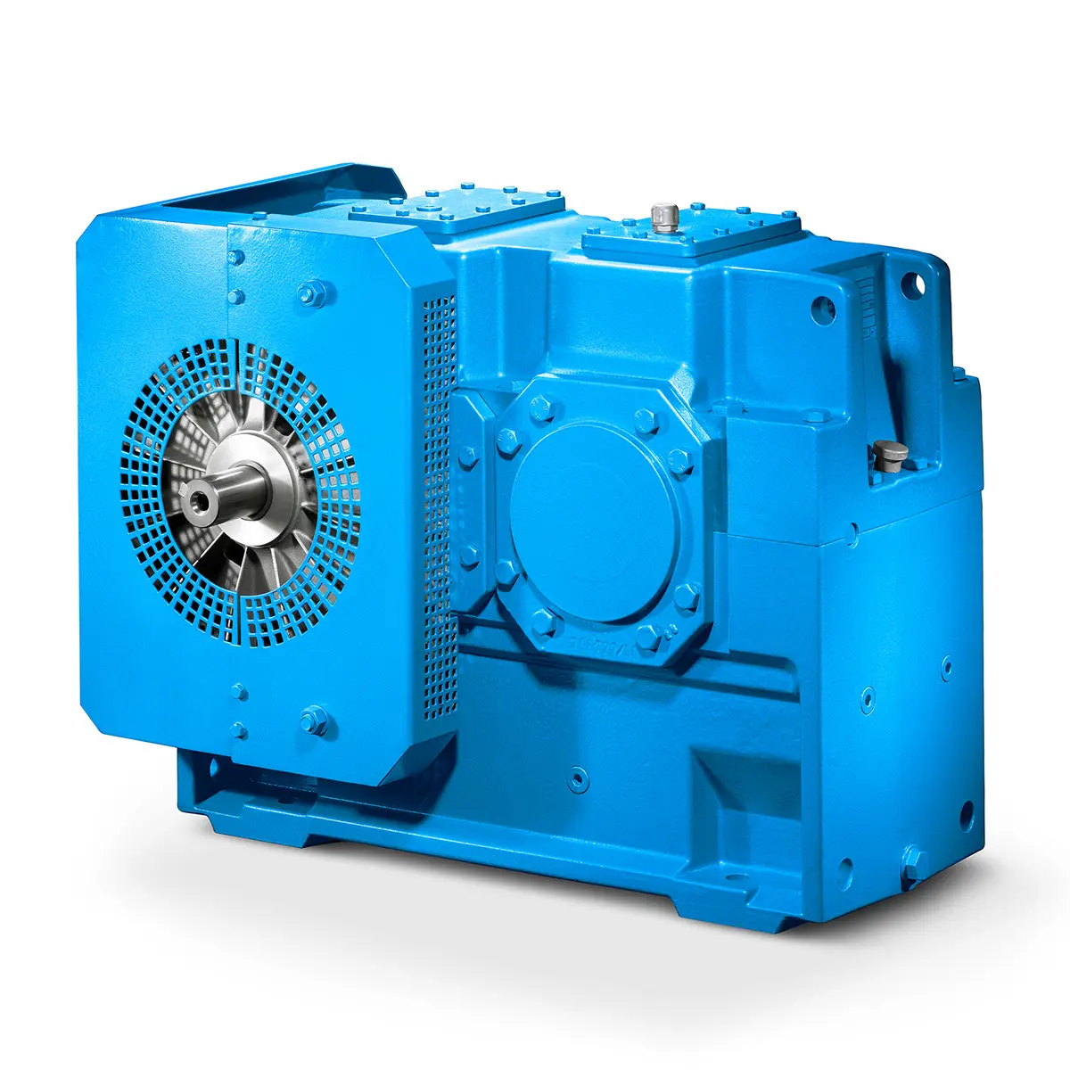
FLENDER Helical Gear Unit
Flender gear units for lifting and luffing gears
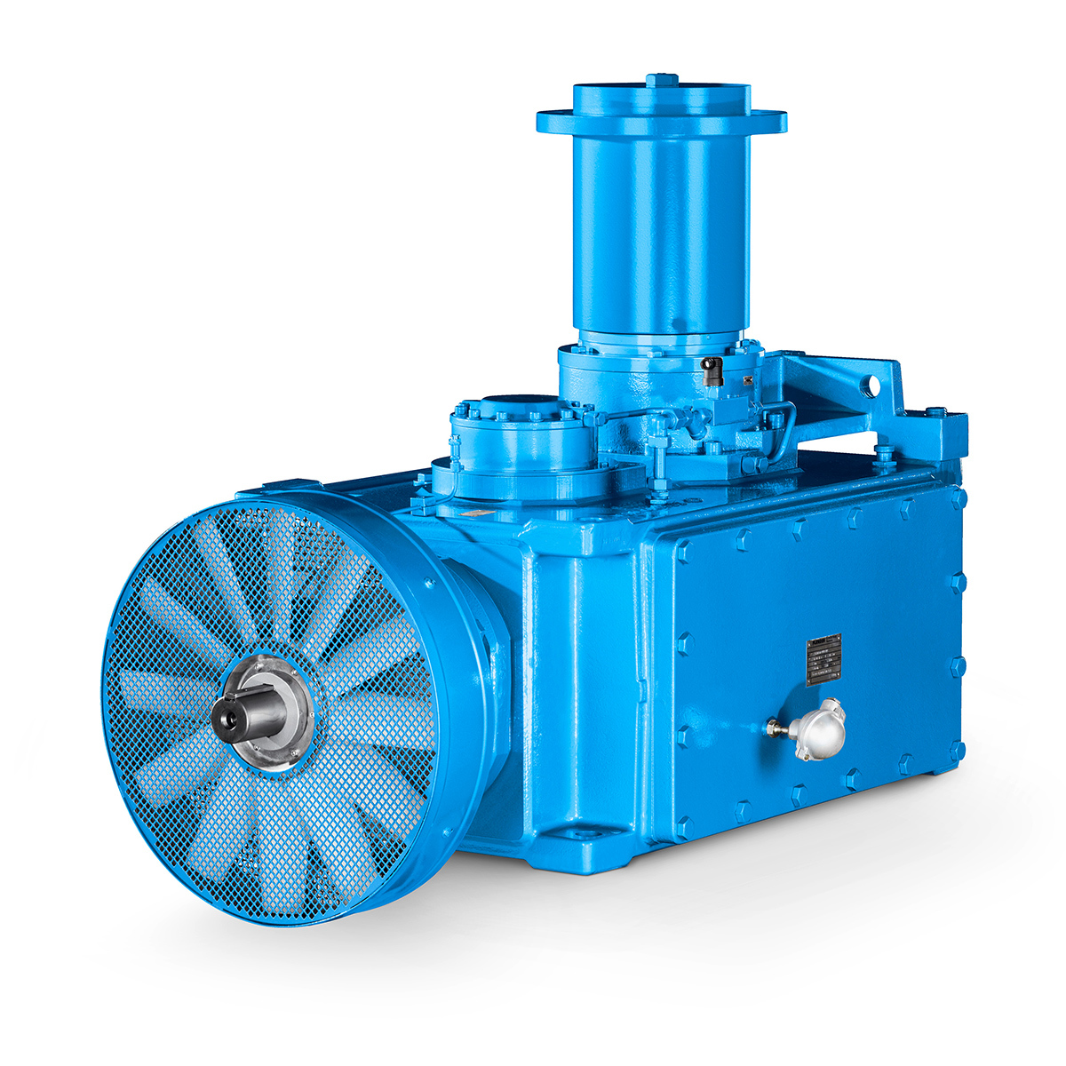
FLENDER Gear Unit gearunit gearbox
Optimal Drive Solution For Maximum Performance
Strongly operating against biodegradable constituents
SINGLE SCREW Special industry dedicated gearunit gearbox
Playmaker In The Premium League
Conveyor belts gearunit gearbox
Paper And Pulp Preparation Sections
Operational Reliability Even In Case Of The Highest Ventilation Forces
Reliable Gear Units For High Performance Vertical Conveyors 59/200
Maximum power density – PLANUREX 3 L individual drives for your sugar cane mill
The proven all rounder gearunit gearbox
Stirs and stirs and stirs gearunit gearbox
Flexibility on Board gearunit gearbox
The right gearbox for all Multi-Engine Ships
Reliable Power Generation on board
Maximum performance level, fast deliverable
Efficient and compact – FLENDER Gear Units for Sugar Mills
Extremely strong. Extremely compact. Extremely stressable.
FLENDER Coupling
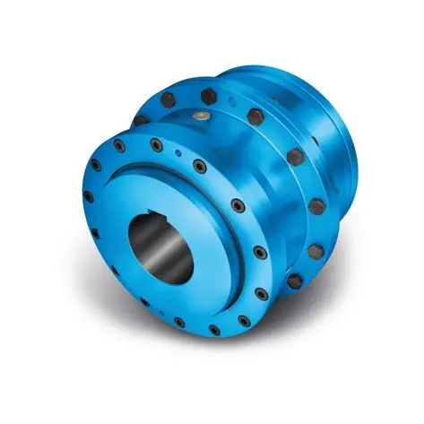
ZAPEX ZW Torsionally Rigid Gear Coupling
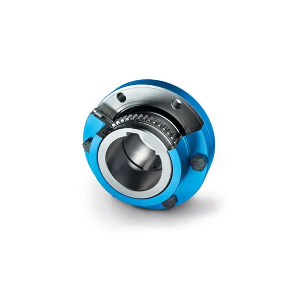
ZAPEX ZN Torsionally Rigid Gear Coupling
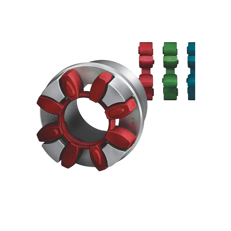
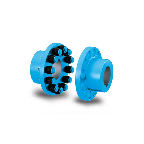
N-EUPEX Flexible high performance Coupling
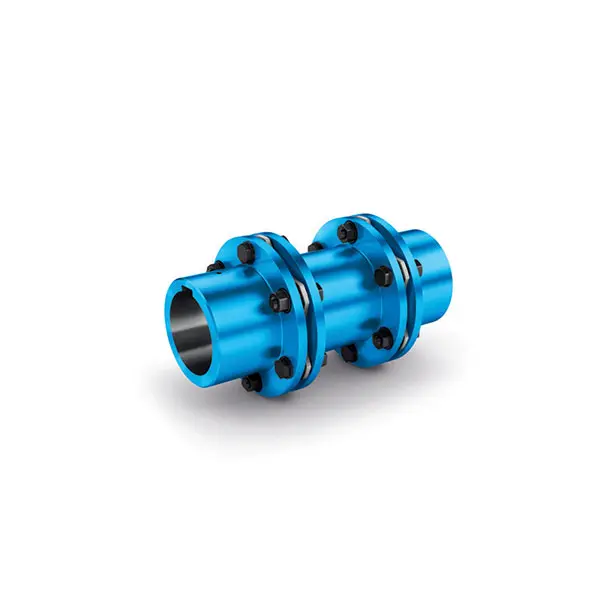
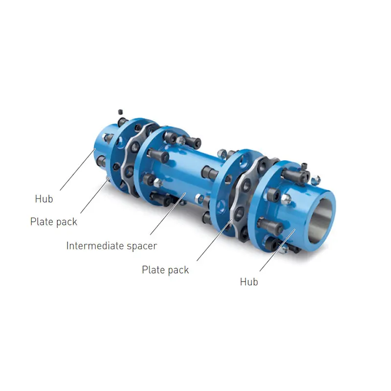
N-ARPEX Torsionally Rigid All-Steel Coupling
ARPEX Torsionally Rigid All-Steel Coupling Spare and Parts
N-EUPEX DS Flexible High Performance Coupling
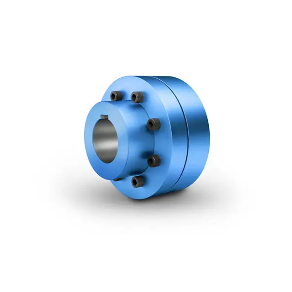
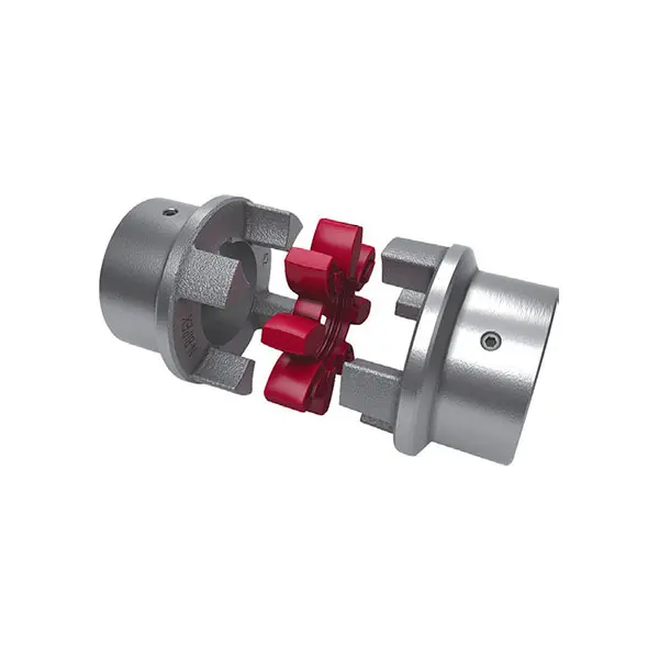
RUPEX Flexible high performance Coupling
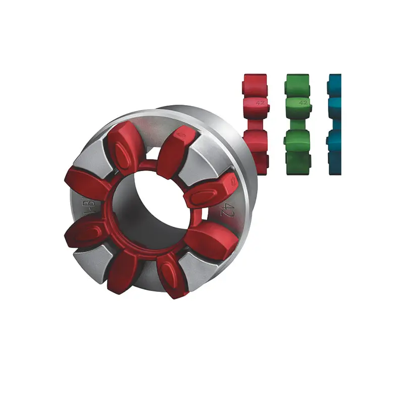
N BIPEX Flexible high performance coupling
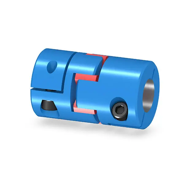
ELPEX B Highly Flexible Coupling
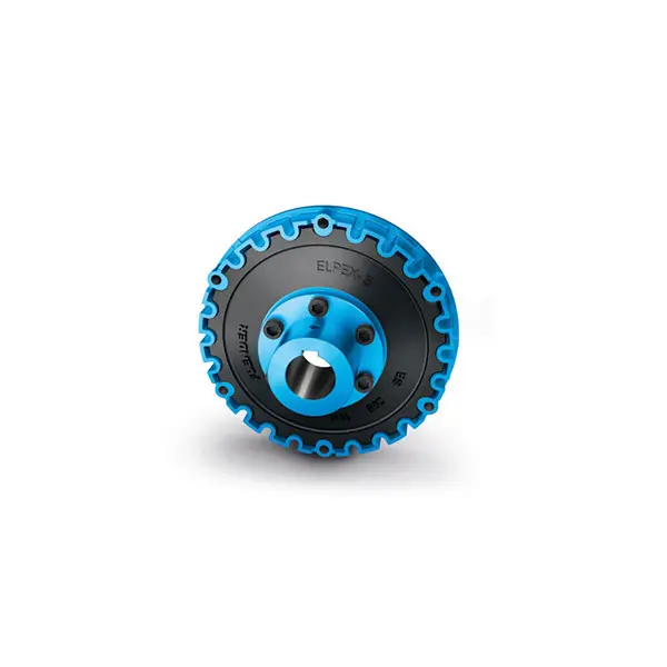
ELPEX S Highly Flexible Coupling high performance
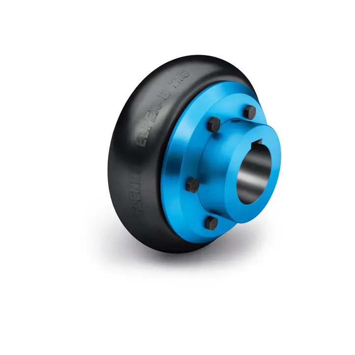
ELPEX Highly Flexible Coupling high performance
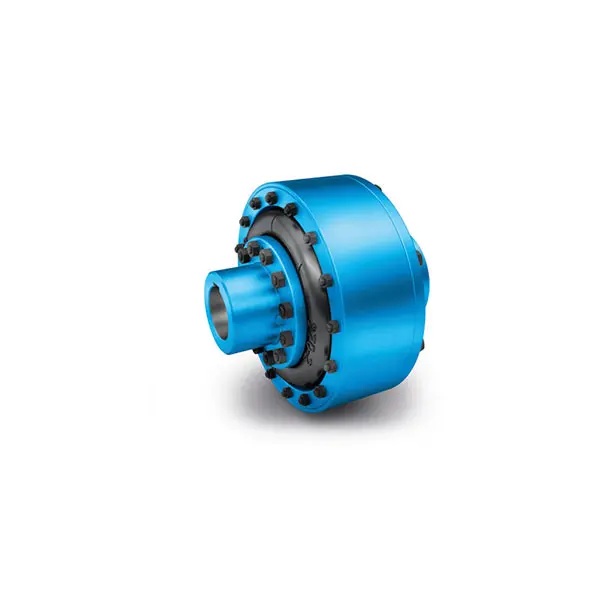
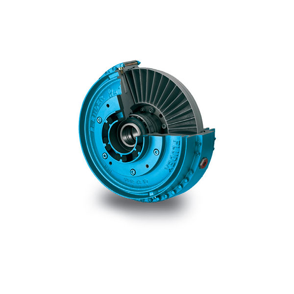
FLUDEX Fluid Coupling high performance
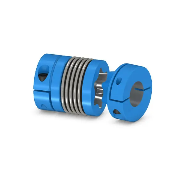
SIPEX Backlash free Coupling high performance
BIPEX S Backlash free Coupling high performance
FLENDER Coupling Spare Parts high performance
SEW Gearmotor
A Gearbox SEW Gear Motor combines an electric motor with a reduction gearbox. This integrated unit delivers controlled speed, higher torque, and dependable mechanical power. In practical terms, it turns fast motor rotation into slower, stronger output at the machine shaft.
The principle is straightforward. The motor produces rotational energy. Internal gears reduce speed and multiply torque. Bearings, seals, lubrication, and housing design then support continuous operation. A conveyor may run quietly while moving heavy cartons. A mixer may rotate slowly without stalling under changing loads. Torque matters.
The International Energy Agency reports that electric motor systems consume roughly half of global electricity. Its Energy Efficiency 2023 analysis also identifies motor efficiency as a major industrial energy-saving opportunity. The U.S. Department of Energy’s Motor Systems Market Assessment further emphasizes the importance of correctly sizing motors, drives, and mechanical transmissions. These findings explain why gearbox selection deserves more attention than simply choosing a powerful motor.
A Gearboxsewgearmotor can support efficient motion when its ratio, torque rating, duty cycle, and mounting position match the application. SEW-EURODRIVE documentation provides valuable technical guidance, but catalog ratings are not a substitute for engineering review. Ambient temperature, shock loading, starts per hour, and maintenance access can change the real result. Small errors matter.
This guide examines how the gearbox and motor work together, how torque travels through the gear stages, and which specifications deserve careful checking. It also questions a common assumption: the largest motor is rarely the best solution. Better performance usually comes from accurate calculation, suitable control, and disciplined maintenance.
An industrial geared motor combines an electric motor with a gearbox in one compact drive unit. The motor produces high-speed rotation, while the gearbox reduces speed and increases usable torque. This arrangement helps machines move conveyors, mixers, lifting systems, and packaging mechanisms with controlled force.
The main components include the motor housing, rotor, stator, gearbox casing, gear sets, output shaft, bearings, seals, and lubricant. The rotor turns inside the stator when electrical current creates a magnetic field. Its rotation passes through several gears. Each gear pair changes speed, torque, and sometimes the rotation direction. The output shaft then transfers motion to the driven machine.
A brake, encoder, or cooling fan may be added for specific applications. A brake holds the load during stopping. An encoder provides feedback about position or speed. Seals keep lubricant inside and dust outside. Small details matter here. Incorrect lubrication can raise temperature quickly. Misalignment may create vibration, noise, and uneven tooth wear.
In practical maintenance, technicians check the nameplate, mounting position, shaft play, and operating temperature. I have found that a quiet gearbox is not always a healthy one; early wear can remain hidden. Inspection records should include load changes and unusual startup behavior. Engineers should also allow for service factors, because real machines rarely operate under perfectly steady loads.
| Data Dimension | Definition or Component | How It Works | Typical Technical Information |
|---|---|---|---|
| Basic Definition | A gear motor is an electric motor combined with a mechanical gearbox. | The motor produces rotational motion, while the gearbox modifies speed and torque before power reaches the driven machine. | Commonly used where controlled speed, increased torque, and compact installation are required. |
| Primary Function | Transmission and speed reduction | Gear engagement reduces output speed and generally increases output torque for a given motor power. | Output speed is determined mainly by motor speed and the selected gear ratio. |
| Electric Motor | The prime mover that converts electrical energy into mechanical rotation. | An electromagnetic field produces torque on the rotor, causing the motor shaft to rotate. | May be an AC induction motor, permanent-magnet motor, or another electric motor type. |
| Gearbox Housing | The rigid enclosure that supports and protects internal transmission parts. | It maintains shaft alignment, contains lubricant, and helps protect gears from contamination. | Usually made from cast iron, aluminum, or engineered metal alloys, depending on load and mounting requirements. |
| Gears | Toothed mechanical elements that transfer motion and force between shafts. | Different gear sizes and tooth arrangements create the required speed ratio, torque multiplication, and rotation direction. | Typical arrangements include helical, spur, bevel, worm, and planetary gear systems. |
| Gear Ratio | The relationship between input speed and output speed. | A higher reduction ratio produces lower output speed and generally higher output torque, subject to efficiency and load limits. | For an ideal reducer: output speed ≈ input speed ÷ reduction ratio. |
| Input Shaft | The shaft that receives rotational power from the motor. | It transfers motor torque to the first gear stage through a direct, coupled, or integrated connection. | Input speed is commonly close to the motor's rated operating speed. |
| Output Shaft | The shaft that delivers reduced-speed mechanical power to the machine. | The final gear stage drives the output shaft at the required speed and torque. | Output arrangements may include solid shafts, hollow shafts, keyed shafts, or flange-mounted connections. |
| Bearings | Rolling or sliding elements that support rotating shafts. | Bearings reduce friction and maintain shaft position under radial and axial loads. | Bearing selection depends on speed, load direction, operating temperature, and expected service life. |
| Seals | Components that help retain lubricant and prevent contamination. | Seals surround shafts or housing joints to limit oil leakage and the entry of dust or moisture. | Seal material and design must be compatible with lubricant, temperature, speed, and environment. |
| Lubrication System | The lubricant and method used to reduce friction and remove heat. | Oil or grease forms a protective film between contacting surfaces, reducing wear and heat generation. | Lubricant choice depends on gear type, operating speed, load, temperature, and installation position. |
| Torque Relationship | Torque is the rotational force available at the shaft. | For a practical gearbox, output torque increases approximately with the reduction ratio but is reduced by transmission losses. | Approximate relationship: output torque ≈ input torque × ratio × efficiency. |
| Transmission Efficiency | The proportion of input mechanical power delivered at the output. | Power is lost mainly through gear meshing, bearing friction, seals, and lubricant resistance. | Efficiency varies with gear design, number of stages, speed, load, lubrication, and operating temperature. |
| Mounting Arrangement | The method used to attach the gear motor to equipment. | Mounting geometry determines how reaction forces are transferred and how the output shaft connects to the load. | Common arrangements include foot-mounted, flange-mounted, shaft-mounted, and torque-arm-supported designs. |
| Direction of Rotation | The clockwise or counterclockwise movement of the output shaft. | Rotation direction depends on motor wiring, gear arrangement, and the number of reversing gear stages. | The required direction should be confirmed before connecting the gear motor to the driven machine. |
| Typical Applications | Equipment requiring controlled rotary motion. | The gear motor supplies appropriate speed and torque for continuous, intermittent, or positioning operations. | Conveyors, mixers, packaging machines, material-handling systems, pumps, hoists, and automated equipment. |
A gearbox SEW gear motor combines an electric motor with a mechanical speed reducer. The motor produces rotational energy, while the gearbox changes its speed and torque. A small motor can therefore move a heavy conveyor, mixer, or lifting mechanism. The relationship is practical: reducing speed usually increases output torque, although friction and heat reduce the final result.
Inside the gearbox, gears transfer motion through different tooth ratios. For example, a 20:1 reduction can turn a 1,400 rpm motor into roughly 70 rpm output speed. The real figure depends on efficiency, load, lubrication, and operating temperature. A 90% efficient reducer loses about 10% of transmitted power as heat. That loss is easy to ignore. It should not be.
Motor and gearbox selection must work as one calculation. The U.S. Department of Energy reports that motor-driven systems consume more than 70% of industrial electricity in the United States. This makes efficiency important beyond the purchase price. A mismatched gearbox may cause excess current, vibration, or premature bearing wear. In field inspections, unusual noise often appears before visible damage. Alignment also matters; even a small coupling error can increase heat and shorten service life. The IEA’s Energy Efficiency 2023 analysis identifies electric motor systems as a major efficiency opportunity across industry. Yet efficiency ratings alone cannot predict performance. Real conditions matter: starts per hour, shock loads, dust, ambient temperature, and maintenance quality. A better design leaves operating margin, but excessive oversizing wastes energy.
A motor supplies high rotational speed, while the gearbox reduces speed and increases usable torque. This chart uses a constant motor speed of 1,750 rpm. Output speed is calculated as motor speed ÷ gear ratio. For example, a 10:1 reduction produces approximately 175 rpm at the gearbox output. In practical applications, output torque is also affected by gearbox efficiency, load, and operating conditions.
A gearbox gear motor combines an electric motor with reduction gears to control speed and increase usable torque. The gearbox receives high-speed rotation from the motor. Its gears then transfer motion through several stages. This arrangement supports conveyors, mixers, lifts, and packaging equipment. In real installations, mounting position and load cycles matter as much as rated power.
Helical gearboxes use angled teeth that engage smoothly and quietly. They suit continuous-duty conveyors and automated production lines. Parallel-shaft gearboxes provide a compact layout when the motor and output shaft need offset alignment. Bevel-helical gearboxes change the direction of rotation, often by 90 degrees. They work well with right-angle drives, where floor space is limited. Their tooth contact remains efficient under substantial loads.
Worm gearboxes offer high reduction in a short housing. They run quietly, but sliding contact can create more heat and lower efficiency. Cooling and lubrication deserve careful inspection. Planetary gearboxes distribute load across multiple gears, delivering high torque from a compact package. They are useful in demanding positioning and lifting applications. The best choice is not always the most powerful one. I have seen oversized units waste energy and complicate maintenance. A smaller gearbox may perform better when its service factor, duty cycle, and output speed match the machine. That judgment requires actual operating data, not only a catalog rating.
A gearbox electric motor converts electrical energy into controlled mechanical motion. The motor creates rotation at the input shaft. Inside the gearbox, connected gears transfer this rotation toward the output shaft. Each gear pair changes speed, torque, or rotational direction.
A small input gear may drive a larger gear. The output then turns more slowly, but with greater torque. This reduction helps move conveyors, mixers, lifts, and other demanding equipment. Bearings support the shafts and limit unwanted friction. Lubricant covers the tooth surfaces, reducing heat and wear during operation.
The process sounds simple. It is not always simple.
Gear tooth shape, gear ratio, shaft alignment, and load size all affect performance. For example, excessive side loading can damage bearings even when the motor rating appears suitable. Backlash between teeth may also create a slight delay before the output responds. That detail is easy to overlook.
In practical maintenance, technicians check unusual noise, rising temperature, oil leakage, and vibration. These signs often appear before a serious failure. The housing should remain secure, and the output shaft must connect smoothly with the driven machine. A clean installation matters more than many people expect. Even a correct gearbox can perform poorly when alignment is careless. Efficiency also changes with load, temperature, lubrication condition, and operating time. As a result, published ratings should guide decisions, not replace measured inspection.
Selecting a gear motor begins with the load, not the catalog image. Define torque, speed, duty cycle, and starting frequency. A conveyor carrying wet cartons needs different protection than a clean packaging axis. Check the required output torque at the shaft, then add a service factor for shock loads and frequent starts.
The International Energy Agency reports that electric motors consume roughly half of global electricity. This makes efficiency a practical selection issue, not a decorative specification. Choose an appropriate efficiency class, ratio, and motor size. Oversizing can increase purchase cost, heat, and energy losses. Undersizing may cause overheating during acceleration. Neither choice is clever.
Match the gearbox to the application. Helical units suit efficient, continuous conveying. Bevel designs support right-angle layouts. Worm gearboxes save space, but may lose more energy through sliding contact. The U.S. Department of Energy’s 2021 Motor Systems Market Assessment identifies pumping, fans, and compressed-air equipment as major industrial motor loads. These systems often benefit from variable-speed control, especially when demand changes during a shift.
Installation details matter too. Confirm mounting position, shaft direction, ambient temperature, ingress protection, and brake requirements. A dusty washdown area may require sealed construction and corrosion-resistant hardware. I have seen selection sheets that looked complete but ignored back-driving. That small omission can stop a lifting mechanism from holding safely. Review the real operating pattern, not only the rated load.